Hello,
Was looking through my assorted tubes and found a handfull of GE 8136 Beam Tetrodes that i would like to build an OTL headphone amp with.
Not sure if anyone has actiually used this tube for an audio amp before but looking through the datasheet they seem to me at least like they could work.
First things first, i am not looking to make something necessarily objectivly good.
This is just to have some fun by designing an amp of my own with something thats not been done to death already like the 12A-whatever/ECC tubes. They make for great amps but thats not what this project is about 😛
The goals with this are:
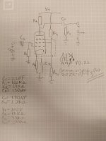
I'm fairly new to designing amps, especially tube ones(Done a small amount of solid state stuff as cource work) so i expect this to need a lot of work. I havent gotten much further than looking at the datasheet and speculating but i threw together a sketch of what i am thinking so far.
I have no idea what to do with the screen with an OTL tetrode so for now in the sketch its just voltage divided to sit at ~125V plucked from the datasheets typical operation.
Other than that i am thinking of a V+ = 200V-300V and Grid Bias = -1.5V as these regions seem fairly linear with regards to the expected input amplitudes( <50mVrms / <0.14Vpp ).
Looking this over one last time before posting i realise that this might have a "huge" voltage output(~70V) and that Ra should be shrunk to something much smaller but i am not entirely sure, its late here so please enlighten me on this matter... 🙂
I have attached a sketch of the topology that came to mind first but it is probably going to need quite a bit of work. Happy to hear your thoughts on it as long as its not "wow this is dumb" or "why would you build this" but do feel free to point out any flaws in a constructive way!
Was looking through my assorted tubes and found a handfull of GE 8136 Beam Tetrodes that i would like to build an OTL headphone amp with.
Not sure if anyone has actiually used this tube for an audio amp before but looking through the datasheet they seem to me at least like they could work.
First things first, i am not looking to make something necessarily objectivly good.
This is just to have some fun by designing an amp of my own with something thats not been done to death already like the 12A-whatever/ECC tubes. They make for great amps but thats not what this project is about 😛
The goals with this are:
- To be able to drive my 50 Ohm headphones
- Having a good time designing and building
- Learning about general tube amp design
- Learning about the specific design conciderations for Beam Tetrodes
- Designing and building a clean PSU that can be used in this and later projects
I'm fairly new to designing amps, especially tube ones(Done a small amount of solid state stuff as cource work) so i expect this to need a lot of work. I havent gotten much further than looking at the datasheet and speculating but i threw together a sketch of what i am thinking so far.
I have no idea what to do with the screen with an OTL tetrode so for now in the sketch its just voltage divided to sit at ~125V plucked from the datasheets typical operation.
Other than that i am thinking of a V+ = 200V-300V and Grid Bias = -1.5V as these regions seem fairly linear with regards to the expected input amplitudes( <50mVrms / <0.14Vpp ).
Looking this over one last time before posting i realise that this might have a "huge" voltage output(~70V) and that Ra should be shrunk to something much smaller but i am not entirely sure, its late here so please enlighten me on this matter... 🙂
I have attached a sketch of the topology that came to mind first but it is probably going to need quite a bit of work. Happy to hear your thoughts on it as long as its not "wow this is dumb" or "why would you build this" but do feel free to point out any flaws in a constructive way!
Attachments

Good point, didnt think about that. I calculated the plate resistance from the datasheet at the operating point i was thinking and its about 500k 😓Pentode, unless triode-connected, is poor choice for OTL because of its high plate resistance, typically tens of kOhms. With 50 Ohm lheadphone as load, only about 0.1% of output power will get to the headphone.
Try this schematic: https://www.diyaudio.com/community/threads/tim-williams-se-otl-amplifier-questions.332614/
https://www.diyaudio.com/community/attachments/6dk6-otl-gif.729436/
https://www.seventransistorlabs.com/tmoranwms/Circuits/PCF_6DK6_OTL.gif
https://www.seventransistorlabs.com/tmoranwms/Data_6DK6.gif
It's triode connected and cathode follower. Maybe one tube is enough to drive 50 ohms h/p. I might want to build the model first to verify.
Attachments
Last edited:
Also you probably want a bleed resistor on the output to prevent it charging up to the anode voltage when the headphone is unplugged.
I do have that in the sketch I drew myself, but yes that should be added if I would follow the sketch Koonw posted.Also you probably want a bleed resistor on the output to prevent it charging up to the anode voltage when the headphone is unplugged.
Thank you, I saw that schematic when looking around but just following that kind of takes away from my goals with this project. It's not so much about using the 8136 as it is about designing my own thing and building that. Might use that sketch for some inspiration for topology though, especially for the triode connected pentode bit 😀Try this schematic: https://www.diyaudio.com/community/threads/tim-williams-se-otl-amplifier-questions.332614/
https://www.diyaudio.com/community/attachments/6dk6-otl-gif.729436/
https://www.seventransistorlabs.com/tmoranwms/Circuits/PCF_6DK6_OTL.gif
https://www.seventransistorlabs.com/tmoranwms/Data_6DK6.gif
It's triode connected and cathode follower. Maybe one tube is enough to drive 50 ohms h/p. I might want to build the model first to verify.
Could someone explain what the 47u cap, 47k resistor and 100mH inductor are doing there though? Especially the inductor I feel like I haven't seen between +- output before 🙂
Edit:
Also damn that's a really big output cap 1000uF seems fairly excessive?
🙂
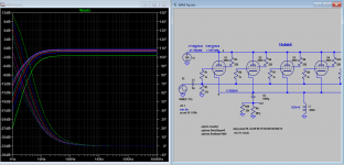
I just built this model, which must be made fairly accurate for the sims that depend on it. Once you have the model it's easier to do with software rather than hardware so you have some ideas what to expect in real project. By connecting the screen to plate you got triode mode, same way you can do the same with the software. The part values you mentioned is RC or RL pairs with the correct time constant needed in frequency reponse of the amp. If the load is low, then C or L must be increased. I also posted the sim file, you can open it with LTspice if you want.
Attachments
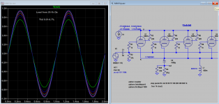

That's with 15 of them per chanel though, they are only pushing 0.06A through the load together. Only using two or three that's not going to work. Especially as I think I will have a lot less input signal than simulated too.It's doesn't need to be in triode mode, pentode mode can do just as well.
The gain (or gm transconductance) drops as the number of tubes are reduced, but it still should work, of course output is also reduced but distortion remain low.
With 15 tubes the max. output is 1W with 1k load 2% thd, with 1 tube it's only a few mW, you only need more tubes if you you wanted more power (also add more gain). If you need more gain alternative is to add another gain stage.
With 15 tubes the max. output is 1W with 1k load 2% thd, with 1 tube it's only a few mW, you only need more tubes if you you wanted more power (also add more gain). If you need more gain alternative is to add another gain stage.
Attachments
Last edited:
Alright, seems like you're loosing signal strength through that setup tho, less of an amp and more of a resistor 😅 but I get the point.The gain (or gm transconductance) drops as the number of tubes are reduced, but it still should work, of course output is also reduced but distortion remain low.
With 15 tubes the max. output is 1W with 1k load 2% thd, with 1 tube it's only a few mW, you only need more tubes if you you wanted more power (also add more gain). If you need more gain alternative is to add another gain stage.
Would some sort of push pull do any good here? Concertina phase splitter with a 12ax7 or something into a push pull of my 8136s? Alternatively a solid state stage either on the input or output to push some more power? (feels odd to put a solid state stage after a beam tetrode though 😂😂)
I tried 6F12p pentode, gain about 10/1k with single tube or 120 with 15 tubes (2W/1K), that is almost double over 8136. Try EL84.. or some other high gm pentode..
I mean sure I could use EL84s, I have a handfull around, but I feel like this is starting to deviate way off my goals here so I might just grab another tube from my box and give it another crack.I tried 6F12p pentode, gain about 10/1k with single tube or 120 with 15 tubes (2W/1K), that is almost double over 8136. Try EL84.. or some other high gm pentode..
These tubes don't seem viable when I only have six of them to last me for as long as I want to use this amp. Maybe I should do something with 6/12AU6 tubes, got an absolute tone of those. Also have a bunch of E91H tubes, might be interesting to built a heptode OTL amp, probably a really bad idea but I mean it's not like I'll be able to get the needed transformers any time soon so might as well? 😀
Yes, I think hepode/ pentode mode otl is great, just look at Futterman OTL3. https://audio-circuit.dk/downloads/futterman/Futterman-OTL3-pwr-sch.pdf
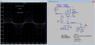
But you can use our simple pentode cathode follower, use floating screen supply with zener instead. You can use single pole or bipolar supply preferable less than 300v or +-150V.
But you can use our simple pentode cathode follower, use floating screen supply with zener instead. You can use single pole or bipolar supply preferable less than 300v or +-150V.
Last edited:
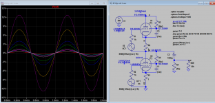
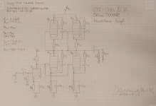
Now this looks really good! I looked through all of my tubes and found another 11 8136 too so right now i am thinking something along the lines of this:Here is the sketch of SEPP (Single Ended Push Pull) 8136 OTL. It's 4-5 times more powerful the previous choke load version.
Input stage to boost the ~50mVrms signal maybe 5-10x and then feeding that into two paralell SEPP pairs.
Not sure what to choose as the input tube though. The easy choise would probably be a 12au7 but id want to use something else when im already using what feels like a silly amount of tubes. Maybe a 6AU6 or two in triode mode? Havent looked at the datasheet to see how viable that would be though
This is where im at at the moment for the schematic, i think this would be enough for a pair of 50 Ohm headphones with the extra triode voltage gain stage but i dont know what tube to use there. Looked at the 12/6AU6 a bit and in triode mode i think it might do the job but i could go for an ECC81/82/83/88. The pull towards the 6AU6 is that i dont need two V+ levels and could run it at the 400-450 V of the SEPP stage, with the ECC options i belive i would need to have a 150-300V supply as well so they were more attractive when it was just a bunch of 8136s in paralell.
Not really keen on using more 8136s for the input stage, would like to use something else. I have a bunch of different tubes available but the ones mentioned are the ones that stick out to me as obvious candidates for the job among the ones i already have 🙂
edit
also wow this amp is going to eat through all my B7G sockets and then some. Im thinking about 3D printing some. Not sure how well they would take the heat though :/
Attachments
Also damn that's a really big output cap 1000uF seems fairly excessive?
That gives -3dB at 20Hz, which is just about acceptable.
Ideally it would be more like 10,000uF, which gives -3dB at 2Hz and low phase shift.
Is that from the inductor and capacitor acting as a LC high-pass filter?That gives -3dB at 20Hz, which is just about acceptable.
Ideally it would be more like 10,000uF, which gives -3dB at 2Hz and low phase shift.
This is independent of the inductor, and just for the RC high pass filter that includes the load.Is that from the inductor and capacitor acting as a LC high-pass filter?
The inductor will further roll off the bass and add distortion when you include its effects.
It is used to provide a path for the DC bias current of the (single ended) output tubes.
Last edited:
- Home
- Amplifiers
- Tubes / Valves
- GE 8136 OTL tube headphone amp idea