Alright. Took me a bit to see the maths but yes, that is correct for that circuit 🙂This is independent of the inductor, and just for the RC high pass filter that includes the load.
The inductor will further roll off the bass and add distortion when you include its effects.
It is used to provide a path for the DC bias current of the (single ended) output tubes.
gona have to calculate the equivalent resistance from my circuit tomorrow to size out that cap, probably going to end up with a similarly quite large cap.
I assume I can't just stick a 125F supercap in there because of ESR? 😀
I plead nolo contendere.I assume I can't just stick a 125F supercap in there because of ESR?
Last edited:
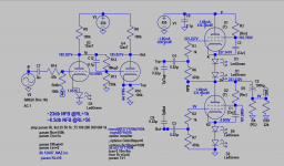
You need a phase spilter or anti-phase driver, for SEPP both tubes are driven in anti-phase, unless SRPP. LTP (Long Tail Pairs) is commonly used, the top drive is boostrapped so to achieve equal drive level for each top and bottom tube and about 20 db negative feedback provides about overall unity gain. If you need more gain you can design LTP stage around pentode tube or add another gain stage. The constant current source (CCS) can be provided by three leg LM337, and resistor limiting current to 2mA, 1mA for each 12AX7.
Attachments
Oh I must have read SEPP as SRPP as that's what I drew on my paper. It was getting kind of late 🙂You need a phase spilter or anti-phase driver, for SEPP both tubes are driven in anti-phase, unless SRPP. LTP (Long Tail Pairs) is commonly used, the top drive is boostrapped so to achieve equal drive level for each top and bottom tube and about 20 db negative feedback provides about overall unity gain. If you need more gain you can design LTP stage around pentode tube or add another gain stage. The constant current source (CCS) can be provided by three leg LM337, and resistor limiting current to 2mA, 1mA for each 12AX7.
SRPP would make the PSU easier if I used something like a 6AU6 for the input stage as I would only need one 450V rail rather than a 450V and a 200V but would this be much worse performance wise?
Is the same, how you derived V+1? Are u going to direct couple to SRPP output stage? Maybe cap coupled is easier.
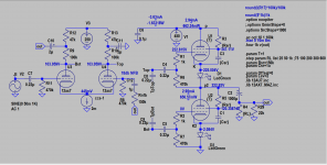
For SEPP driver, current drawn is 2ma, just use resistor drop voltage 450V-250V=200V/2ma=100k, with filter cap of 10-22u can do. There is not need for another xformer tap as current demand is low so no performance degrade is expected. If you're worry use zeners regulation (say 100Vx2+50Vx1).
In my SEPP sch, the gain can be higher if NFB is relaxed a bit say Rnfb reduces from 100k to 1000k. It's much harder to design SEPP than SRPP as you see from sch, of course you can pick whichever one works best for you. There are many SRPP sch you can refer.
Btw Mullard call your sketch sch SEPP : https://frank.pocnet.net/sheets/129/e/EL86.pdf
https://audioxpress.com/article/The-SPP-Amplifier
Last edited:
Got V1+ from looking at some load lines and bias points I found around the Web for the 6au6. Was thinking direct couple but capacitor coupled is probably easier.Is the same, how you derived V+1? Are u going to direct couple to SRPP output stage? Maybe cap coupled is easier.
For SEPP driver, current drawn is 2ma, just use resistor drop voltage 450V-250V=200V/2ma=100k, with filter cap of 10-22u can do. There is not need for another xformer tap as current demand is low so no performance degrade is expected. If you're worry use zeners regulation (say 100Vx2+50Vx1).
In my SEPP sch, the gain can be higher if NFB is relaxed a bit say Rnfb reduces from 100k to 1000k. It's much harder to design SEPP than SRPP as you see from sch, of course you can pick whichever one works best for you. There are many SRPP sch you can refer.
Nice to know about the PSUs for the SEPP, that makes that a viable idea. Would probably reduce the NFB to get more gain if I do. Would end up being a lot less silly with only three tubes per chanel too instead of the five I was thinking(though my design could probably be fine with just three tubes if the input stage has some gain).
Also wondering about LTP vs Concertina phase splitters, the Concertina is really simple and only needs a single triode where as the LTP design needs a double triode. This doesn't really make much of a difference to me as the difference is using one or two 12ax7s which is no big deal to me but I would think there are more differences I'm not seeing at a glance 🙂
I would think there are more differences
Concertina is unity-gain (to each output); most other splitters have significant gain. You always need that last touch of gain after a preamp and before your power tubes. So concertina is "always" used with a gain stage before.
So it's always two tubes to drive push-pull. (May not be two bottles.)

It required only 2 tubes (4 sections) such as pentode / triode 6F12p.
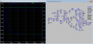
Here I sim the concertina ps version, ps stage is direct couples, and NFB is feed into grid so a larger resistor can be used to avoid loading of the output. 20db NFB is not quite practical with feedback into cathode without causing an arm and leg.
Here I sim the concertina ps version, ps stage is direct couples, and NFB is feed into grid so a larger resistor can be used to avoid loading of the output. 20db NFB is not quite practical with feedback into cathode without causing an arm and leg.
Attachments
Alright, sounds like LTP is the way to go then for a bit of gain 😀 probably with a 12ax7 and zeners to drop the PSU down for it.Concertina is unity-gain (to each output); most other splitters have significant gain. You always need that last touch of gain after a preamp and before your power tubes. So concertina is "always" used with a gain stage before.
So it's always two tubes to drive push-pull. (May not be two bottles.)
Honestly this amp is shaping up to be a lot less silly than I thought a couple of days ago, I mean it's still six tubes to drive some headphones but it's not the 10+ it was looking like for a while there haha
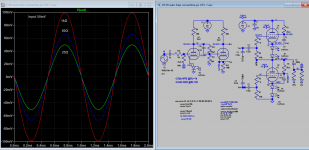
Hi, I must confess 50 ohms is a difficult load for 2w tubes as OTL, it better suit to transformer type. The 15x tubes is just sim of schmatic of another person, not mine. The later LTP and concertina are my design, of course I still not sure it meets your requirement. If you need more suggestion there are other forum members and me here to help out, even your resouce appeared limited.
Last edited:
Must it absolutely be OTL? I've been thinking about a para-feed tube headphone amp using the Sowter 8665.
Maybe a variation of this one:
https://www.bartola.co.uk/valves/2019/12/25/e282f-hp-amp
Maybe a variation of this one:
https://www.bartola.co.uk/valves/2019/12/25/e282f-hp-amp
The LTP design seems to produce slightly over unity gain with a 50 ohm load in your sim, if the feedback is slightly reduced it would do the job I would think 🙂Hi, I must confess 50 ohms is a difficult load for 2w tubes as OTL, it better suit to transformer type. The 15x tubes is just sim of schmatic of another person, not mine. The later LTP andconcertina are my design, of course I still not sure it meets your requirement. If you need more suggestion there are other forum members and me here to help out.
I mean, unless you want to send me some output transformers then yes. I've got everything I'd need for an OTL design already and no money to spend on this hobby and likely won't have for a whileMust it absolutely be OTL? I've been thinking about a para-feed tube headphone amp using the Sowter 8665.
Maybe a variation of this one:
https://www.bartola.co.uk/valves/2019/12/25/e282f-hp-amp
Took a look at what I've got around for the PSU and have decided that it's much much easier to build a 350v V+ supply, that would end up as about 175V over each tube instead of, slightly lower but I belive that should be fine.
Still have yet to decide if I'd rather build SRPP with an input gain stage or SEPP with LTP.
Still have yet to decide if I'd rather build SRPP with an input gain stage or SEPP with LTP.
How come you have the bias of the tubes at - 4V in this schematic? I was thinking more like - 1.5V to get more power out of the tubes? Is it to reduce the quiescent current? At - 4V is be afraid to bottom the tube from looking at the datasheet 🙂It required only 2 tubes (4 sections) such as pentode / triode 6F12p.
Here I sim the concertina ps version, ps stage is direct couples, and NFB is feed into grid so a larger resistor can be used to avoid loading of the output. 20db NFB is not quite practical with feedback into cathode without causing an arm and leg.
Because it's class AB amp, only needs the minimal current to overcome cross-over distortion. By increasing the grid swing it gives more power output.
Ah right but still wouldn't class A and a - 1.5V bias give more power? Of course it would also use a LOT more power but when the output is already struggling I would belive that tradeoff would be worth it? (even if this design in AB seems to work well already! 🙂 )Because it's class AB amp, only needs the minimal current to overcome cross-over distortion. By increasing the grid swing it gives more power output.
Also discovered to my delight that the input signal is going to be more like 100mVrms too rather than 50mVrms as I thought so that's going to make things a bit better too!
Going to summarise everything in another post fairly soon, hopefully later today, so it's clear where everything is and what's left to spec out and design! Really appreciate the help, the simulations you've done are amazing for helping me along! 😀
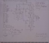
Well stuff got in the way of posting for a bit but here is where I am at now. Didn't draw in the negative feedback because I am not entirely sure how to do that right. I think I want to have it be adjustable too. I did drawn in a switch to swap between the LED class AB bias and a resistor class A bias because I want to experiment a bit. Might remove that feature later, don't know.
Haven't simulated the circuit, just done hand calculations for estimating loads and the filters but I belive this should work alright 🙂
Got all the stuff for the PSU, just got to pick some diodes or grab a suitable bridge rectifier. Also built a suitable box to cram all of this into(but any box you build is always going to be too small 😂)
Attachments
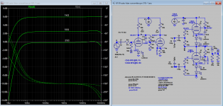
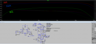
Was finaly able to put away some time to simulate everything in LTSpice, played around a small amount with some values untill i ended up with whats in the picture which i am fairly happy with! About 2dB gain for the audible spectrum with a 50ohm load, could go for more by making R12 bigger but i found this to be a fairly nice balance between gain and flattness of the gain curve 🙂
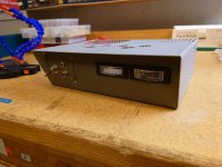
Been working away at a nice looking box for the thing too, pretty much finished and im fairly happy with the result! 😀 The VU meters are only temp units, going to replace those once i start actiually building the thing. Probably going to end up going for a 50s looking teal/cream paintjob 🙂
Been working away at a nice looking box for the thing too, pretty much finished and im fairly happy with the result! 😀 The VU meters are only temp units, going to replace those once i start actiually building the thing. Probably going to end up going for a 50s looking teal/cream paintjob 🙂
Attachments

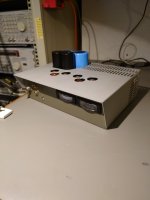
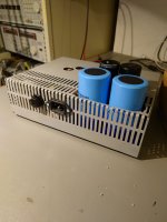
Made a lot of progress thanks to some good friends and a lot of hours in the lab 😀
Might not look like much maybe but now the transformers are mounted, a holder for the caps has been CADed, 3D printed and mounted and a mains filter+fuse has been attached at the rear.
Also constructed a circut to drive the VU meters. Its nothing too difficult, basically a half wave rectifier split supply from the fillament transformer and an OP-amp buffer+rectifier for each channel using the TL072 JFET OP amp. I can post a schematic if anyone is interested(tho i pretty much just ripped it off the web so might be faster to do a web search 😛 )
Whats left to do now is pretty much doing the actual electronics, putting some feet on it and paint. Next thing i am working on is finalising the PSU design and building and testing it. Its not a difficult design but i havent laid out the entire thing with all the caps before, just drawn in the big caps, a full bridge and an RC filter before but obv its going to need some bleed resistors, inrush limiting(yeah im sure its probably fine without because the power trafo will saturate but i only have this one and i want to be extra nice too it) and ceramics to make it safe and good.
Also have not decided how i want to build the CCS yet, its only going to be pulling 2mA so i am thinking LM317/337 based but as it is for the first stage im slightly concerned about how noisy it will be. Might make a current mirror with some NPNs instead though i dont know if that is any better, that would be just to get to use some sweet looking TO-3 transistors 😀
Attachments
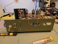
After a lot of PSU struggles I have all the tubes lit at least! Was really nice to see that after all these weeks of work!
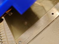
Did the last of the "make it work" wiring and plugged it in and the big PSU filter caps arced to ground in a pretty dang loud bang because of a small mistake but nothing took any damage from what I can tell. Never heard an amp that loud before 😂 made a nice mark on the case too
Did the last of the "make it work" wiring and plugged it in and the big PSU filter caps arced to ground in a pretty dang loud bang because of a small mistake but nothing took any damage from what I can tell. Never heard an amp that loud before 😂 made a nice mark on the case too
Attachments
Long time no update!
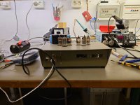
This amp build has gone through a lot at this point, struggled with the power transformer giving too much voltage and built a regulator and when I finally got the circuit powered up I had a lot of weird issues because I honestly did not build the circuit very well.
So I tore it apart and rebuilt it much much cleaner, redid how I mount the tube sockets, removed the VU meters and changed the circuit to have no CCS and no LEDs because they seemed to be causing issues along with other fixes. I'll post an LTSpice picture once I draw that up.
Just finished the first test and it's not good. The distortion is off the charts bad at any alright level and the max volume isn't great either. I'll give it one round of troubleshooting but after that it's going on a shelf as decoration or getting scrapped for parts :/
At least this time both channels are behaving the same and the circuit is built in a way where I can debug it much easier 🙂
Attachments

Last edited:
- Home
- Amplifiers
- Tubes / Valves
- GE 8136 OTL tube headphone amp idea