Banned
Joined 2021
Banned
Joined 2021

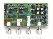
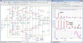
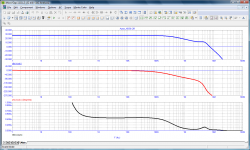
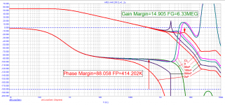
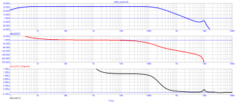
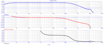
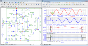
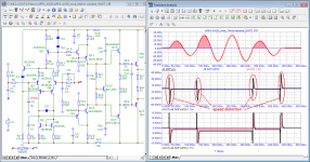
Many radio amateurs liked the APEX AX17 circuit and began to clone it. The disadvantage of the original circuit is a high cutoff frequency from below. Therefore, many radio amateurs began to increase the capacitance of capacitors: input capacito and in the negative feedback circuit. Due to the tracking power of the input stage, it is little affected by changes in the resistance of the signal source (volume control potentiometer). For those who are going to repeat it, I would recommend using a Baxandall pair in the voltage amplifier (as is done in the AX16 amplifier and others). A pair of Baxandall, due to the tracking power of input repeaters, has a lower input capacitance, and a voltage amplifier with a pair of Baxandall, due to deeper local feedback, introduces less distortion. The amplifier has a relatively high frequency of the first pole - above 20 kHz. Due to this, the output impedance in the entire sound band is constant. Using a servo control system allows you to remove the input capacitor and the feedback capacitor.
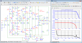
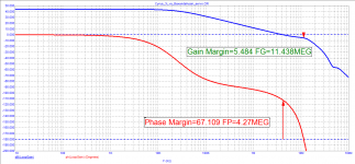
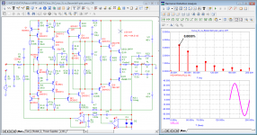
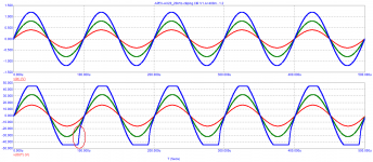
The amplifier has a relatively short signal propagation delay, 65 ns. Due to this, negative feedback copes well with both switching distortion and high-speed distortion. Due to the high frequency of the first pole, the amplifier has a short decay spectrum, the 7th harmonic and above is negligible.
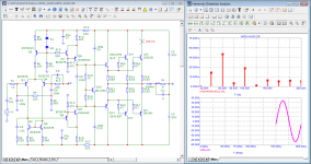
Here are some tests of the modified circuit, maybe someone will be interested
The amplifier has a relatively short signal propagation delay, 65 ns. Due to this, negative feedback copes well with both switching distortion and high-speed distortion. Due to the high frequency of the first pole, the amplifier has a short decay spectrum, the 7th harmonic and above is negligible.
Here are some tests of the modified circuit, maybe someone will be interested
Attachments
-
 01_Cyrus_3i_Baxandal-pair_servo_Bode.png40.4 KB · Views: 472
 -
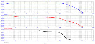
 02_Cyrus_3i_Baxandal-pair_servo_Loop-Gain.png13.5 KB · Views: 430
 -
 03_Cyrus_3i_Baxandal-pair_servo_20kHz-spectr.png39.6 KB · Views: 385
 -
 04_Cyrus_3i_Baxandal-pair_servo_1W_20kHz-spectr.png41.6 KB · Views: 399
 -
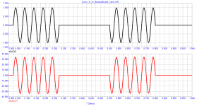 05_Cyrus_3i_Baxandal-pair_servo_20Hz-burst.png12.9 KB · Views: 432
Last edited:
First of all, I would like to express my gratitude to the author of the topic.
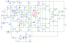
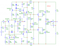
Looking through the diagrams, I noticed the APEX HD50 diagram and typed in its model. It immediately became clear that the circuit was an obvious typo, the resistor R27 should be a resistance of 10 Ohms, not 10 kOhms.
But even with the typo corrected, the amplifier model is unstable on a reactive load. Even adding an inductor at the output of the amplifier does not completely solve the problem. The signal propagation delay (tPD) is 450 ns, which is clearly a lot for high-quality sound amplification.
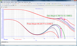
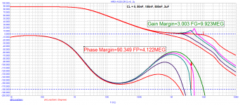
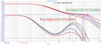
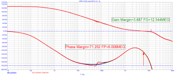
An analysis of two graphs (Bode and Loop Gain) allows us to say that the scheme is very “raw” and needs to be improved in terms of correction.
Best regards
Petr
Looking through the diagrams, I noticed the APEX HD50 diagram and typed in its model. It immediately became clear that the circuit was an obvious typo, the resistor R27 should be a resistance of 10 Ohms, not 10 kOhms.
But even with the typo corrected, the amplifier model is unstable on a reactive load. Even adding an inductor at the output of the amplifier does not completely solve the problem. The signal propagation delay (tPD) is 450 ns, which is clearly a lot for high-quality sound amplification.
An analysis of two graphs (Bode and Loop Gain) allows us to say that the scheme is very “raw” and needs to be improved in terms of correction.
Best regards
Petr
Attachments
Okpetr_2009
And look at the scheme of the Apex AX-20. For some reason, it sometimes also behaves not stable. Can you tell me why?
The operation of the APEX A40 amplifier model. The model was typed using Bob Cordell's spice models.
I hope that there is a typo in the circuit, otherwise the amplifier is inoperable with such parameters.
Attachments
petr_2009
And look at the scheme of the Apex AX-20. For some reason, it sometimes also behaves not stable. Can you tell me why?
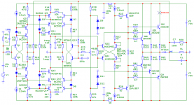
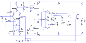
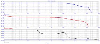
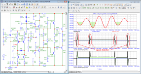
The output of the APEX AX20 has neither a Zobel circuit nor an inductor. On a reactive load, the stability of work is questionable. When clipping, a latch occurs in the lower arm of the output stage.
The signal propagation delay time is more than 1 µs! For high-quality sound amplification, it should not exceed 50 ... 100 ns
Attachments
1. where exactly is the typo in A40?
2. Methods for improving the AX20 without a cardinal deep alteration of the boards?
PS^ you have an AX-14 scheme in the picture. in the AX-20, the output triplet. (AX-14 is just pretty stable.)
2. Methods for improving the AX20 without a cardinal deep alteration of the boards?
PS^ you have an AX-14 scheme in the picture. in the AX-20, the output triplet. (AX-14 is just pretty stable.)
Last edited:
Yes, you are right, I was inattentivePS^ you have an AX-14 scheme in the picture. in the AX-20, the output triplet. (AX-14 is just pretty stable.)
Attachments

and? I'm not quite perfect at this. to read the graphs and understand everything. Seems stable enough, or am I wrong? what distortions does the program produce? and you can answer the previous questions (what is wrong in the A40 scheme and how can the ah-20 be improved)
they are in diode inclusion, this will not affect anything judging by the graphs.in A40 q24 in yours bd140. in original is bd139
miss by 30 degrees - is it stable? but it will work.Seems stable enough, or am I wrong?
Last edited:
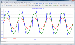
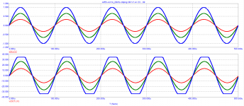
in models AX14, AX20 I missed an important clipping diode. So I'm re-posting the charts.
Attachments
-
 01_APEX_AX20_SCH.png13.2 KB · Views: 295
 -
 02_APEX_AX20_Bode.png9.4 KB · Views: 258
 -
 03_APEX_AX20_Loop-Gain.png19.1 KB · Views: 168
 -
 04_APEX_AX20_20kHz-clipping.png10.3 KB · Views: 261
 -
 01_APEX AX14_SCH.png30.7 KB · Views: 297
 -
 02_APEX AX14_Bode.png9.5 KB · Views: 246
 -
 03_APEX AX14_Loop-Gain.png20.4 KB · Views: 170
 -
 04_APEX AX14_20kHz-clipping.png11.3 KB · Views: 266

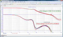
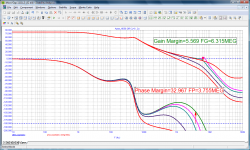
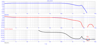
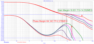
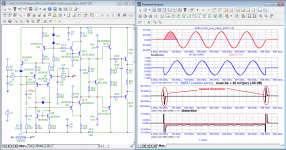
The modified APEX AX20 amplifier has a high loop gain and will perform well when measured with Audioprecision, i.e. in steady state.
But the signal propagation delay is very high (according to Jiri Dostal's calculations, it should be 8 ns, and also according to David Hafler). There is a statement by Cyrill Hammer about amplifiers with negative feedback, it also coincides with the conclusions and calculations of Jiri Dostal.
The sound of such amplifiers is usually "dead", so high-speed distortion is nothing more than a loss of micro-level information of the sound material.
Attachments
"the loop gain graph, the gain margin is small" - I see 71.2 is that not enough??
"signal propagation delay is very high" - and how to fix (improve) it?
"miss by 30 degrees - is it stable? but it will work." - where is it on the graph, please explain, I don't see it.
"signal propagation delay is very high" - and how to fix (improve) it?
"miss by 30 degrees - is it stable? but it will work." - where is it on the graph, please explain, I don't see it.
Last edited:
- Home
- Amplifiers
- Solid State
- A Directory of Apex Audio Amplifiers