a ok , because it is grounded via 100uF it is not AC feedback ..actually it is also cart loading in orig scheme .. i need to delete 47 k in the input thenStop, stop.
R7 = 1k is a DC feedback, not AC.
Someone, tell us a couple words about "my" YouTube records, mentioned earlier, sampled from vinyl via 2N2222.
Your opinion?
Listening to "Time" right now, sounds nice albeit over puny PC speakers at work.
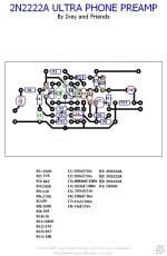
i'm not fan of electrolytic caps on the signal way what this pcb is using.. this can be updated to today standards (film caps)
if you are following mr hans schematic -1uF input should be PP or MKP polypropylene, for output also 15uF film. you can use something available from WIMA MKP/MKS depending of the taste or Kemet/RIFA (10+4.7uF) depending of the space available..even, no need to be 15uF on the output ,10uF will be enough, so one cap will be ok.
if you are following ivey scheme with 15uF input and output electrolytic, then use some "audio" grade like elna silmic 22uf from mouser or nichicon KZ..
if you are following ivey scheme with 15uF input and output electrolytic, then use some "audio" grade like elna silmic 22uf from mouser or nichicon KZ..
Member
Joined 2009
Paid Member
Graham Slee has a thread discussing a similar topology:
1970s Design Indulgence - Graham Slee Audio Forum | HiFi System Components - Page 1
1970s Design Indulgence - Graham Slee Audio Forum | HiFi System Components - Page 1

I have built this circuit and find that it is amazing. Having been used to phono preamps that use opamps, this design provides a very different experience that sits very well with me. So thank you Ivey…
Hopefully somebody can explain the following about the choice of transistors. I’m wondering if it makes sense to match the transistors’ Hfe values for the left and the right channels. I’m not hearing anything untoward in the music produced by my current board. (No matching attempted when building it.) But I am aware that often circuits stabilize or balance The transistor output, making Hfe matching unnecessary.
As I am a noob in electronics I can’t judge if this is the case in Ivey’s circuit. Can someone with a better understanding elaborate?
I was going to use a PN2222A as the front end but found 2SC1815 was somewhat lower noise. I am getting 83db s/n from shure VM15 type 2
How did you measure thisI was going to use a PN2222A as the front end but found 2SC1815 was somewhat lower noise. I am getting 83db s/n from shure VM15 type 2
Hans
1 channel had pn2222A other had 2sc1815
The 2sc 1815 has lower noise with volume up full , cartridge loaded no record playing
The 2sc 1815 has lower noise with volume up full , cartridge loaded no record playing
Theoretically it will have some impact, but in practice it won’t bring any audible benefit.Hi Hans, while you’re here would you mind looking into my question in post #232?
More important is that they have a high Hfe
Hans
ThanksTheoretically it will have some impact, but in practice it won’t bring any audible benefit.
More important is that they have a high Hfe
Hans
@Hans Polak: I gather that lowering the value of R1 increases the gain of the circuit. Because my cart's output is quite low I may want to experiment with going back to 100R, or even using 80-90R. Would you say that this can be done in isolation or would it require other changes to the circuit?
I’ll have a look at it in the coming days@Hans Polak: I gather that lowering the value of R1 increases the gain of the circuit. Because my cart's output is quite low I may want to experiment with going back to 100R, or even using 80-90R. Would you say that this can be done in isolation or would it require other changes to the circuit?
Hans
- Home
- Source & Line
- Analogue Source
- 2N2222A phono preamp