I guess you are right, there must have been an additional tube that kept the HV from running away, and producing hard X-rays.
Whatever the reason for holding the voltage steady, linearity is not the issue when there is negative feedback (example, a sample of the DC regulated voltage back to the grid of the regulator tube).
I do not have a TV schematic handy that shows that complete Flyback, CRT, and Regulator circuit.
And this regulator tube was meant for Pulse Service Regulation of Low Duty Cycle pulses (like the Flyback transformer primary and secondary voltages, for Anode and Screen voltages. The pulse current was very high, and so the plate impedance, rp, was low . . . Right?
I am sure if the tube is used as a input or driver stage, at lower voltage and lower power dissipation there is probably a quiescent setup with a fairly linear range, but finding that point may be hard to do. If it is used at lower current, the rp will probably be higher, making the gain and frequency response dependent on the plate load resistor, following stage grid resistor, and any miller effect capacitance of the next stage.
Again, just my opinions
Last edited:
There may be no equivalent "normal triode".what the advantage is of a beam triode over a 'normal' triode
We "never" use 5,500V on an oxide cathode; the ion bombardment would sand-blast the oxide right off. But here we have a screen grid so very negative of space-charge that ordinary assumptions are changed. This goes along with the pentode trend that a high plate voltage suggests low current, and thus only a low-low G2 voltage is needed (and preferred for low G1 swing). While a "tight" pentode would pass zero current at zero screen voltage; but at 5,500V beyond a loose screen, some current will flow.
https://www.seventransistorlabs.com/tmoranwms/Elec_6HS5.html

Thanks for the link, nice pics. I talked to Morgan Jones about the purpose of those beam plates in the 6HS5:
"They’re there to reduce Cag by screening the grid’s support rods from the anode."
Makes sense, doesn't it. All explained in his Valve Amplfiers 4th Ed, which I subsequently have ordered.
Jan
"They’re there to reduce Cag by screening the grid’s support rods from the anode."
Makes sense, doesn't it. All explained in his Valve Amplfiers 4th Ed, which I subsequently have ordered.
Jan
It is also discussed in Valve Amplifiers 3rd Ed, pg 85, 'Guided Grid or Beam Triodes'. It lowers Cag to below 1pF, and, consequently, the Miller capacitance.Thanks for the link, nice pics. I talked to Morgan Jones about the purpose of those beam plates in the 6HS5:
"They’re there to reduce Cag by screening the grid’s support rods from the anode."
Makes sense, doesn't it. All explained in his Valve Amplfiers 4th Ed, which I subsequently have ordered.
Jan
Jan
Yes, Morgan explicitly mentions the PC97, PC900 and 6GK5.
In some cases the beam plates are not explicitly shown or mentioned in the data sheet.
Jan
In some cases the beam plates are not explicitly shown or mentioned in the data sheet.
Jan

The shield, as the name already implies, shields the grid / cathode from the anode field as electrons can only pass through small slits in the screen. This has several effects:
- Cag is significantly reduced as only the small slit area is effective - this effect is used in the RF triodes like PC900
- In case of the european versions of the HV regulator triodes, the shield effectively protects the grid / cathode from the extremely strong fields as these triodes have been designed to perform the regulation on the secondary side of the flyback transformer in colour TV sets. They run with 25 kV anode voltage and a few mA of current. The american types like 6HS5 were designed to do the same regulation but on the primary side - hence the lower anode voltage and higher current (the max. anode power specs of 30W are identical!). While the american triodes regulated the primary side via pulse current regulation, the european types worked after the secondary rectifier/voltage multiplier cascades on HV DC (the picture tube anode capacitance was the smoothing cap !)
- In addition, µ, Gm and rp are influenced. Typically, these triodes have quite high values for µ allowing for high gains in the regulator stage and thus only requiring low grid voltage swings
Thanks for that clarification! In fact, my first 'real' job was with Philips in Eindhoven, The Netherlands, developing inductive components for color TV.
The high voltage flyback was indeed 25kV as I remember, and we used PL500 as secondary side regulator. Didn't know you Yanks did it at the primary side!
As I'm sure you know, the HV pulse was the result of the very hig dI/dT during the flyback on the line side, and it was a relatively narrow pulse, don't remember details but in the double-digit uS range I think.
To get more energy from such a narrow puls, we tuned the secondary circuit to the 3rd harmonic of the puls to make it look more 'squarish'- with more energy content, thus better regulation.
Those were the days, and I was extremely green!
Yes, I noticed that the 6HS5 requires relatively small grid excursions for significant Ia variations.
Jan
Aha, so you are the one that worked on the "transductor" for picture geometry correction before they found out it could be done with diodes 😎
Mona
Mona
That was the same lab. I remember there was a saturating inductor in series with the field coil, called a 'mouse', don't know why.Aha, so you are the one that worked on the "transductor" for picture geometry correction before they found out it could be done with diodes 😎
Mona
They called it S-correction as it modified the sawtooth wave to look more like an S, less amplitude towards the end.
This was to correct for the non-constant radius of the picture tube screen.
Edit: the saturating inductor had a core you could adjust. With a squares pattern on the picture tube you could adjust for perfect geometry.
I wonder how they did that in production, I can't imagine they adjusted each and every set. Or maybe they did, labour was not as expensive then as it is today. Talking 1960-ies here.
Jan
Last edited:
I've measured some low tube capacitances using a sensitive L meter, with a little wooden stick holding an unclipped meter lead (clipped onto the stick end). (other lead clipped on a tube pin)Wow! That PC900 has 0.365pF anode to grid. I wonder how they measure that!
Then just move the stick a tiny amount to touch or not touch the 2nd tube pin with the clip. Being careful not to move any lead wires. Just take the difference in readings then.
Last edited:
That's smart! I think I even know how to calculate it ☕
I guess you use a relatively high test frequency?
Jan
I guess you use a relatively high test frequency?
Jan
Any modern LCR bridge has the ability to measure pF with 3 decimals at relatively high frequency
Back then probably they had very expensive lab equipment capable of this .
Back then probably they had very expensive lab equipment capable of this .
The plate curves on the beam triode look similar to ones that I generated for a screen driven 6CD6. The plate resistance looks rather high. If I use them, I might do it at a lower plate voltage with some feedback to lower the apparent plate resistance, "Schade" style. The transconductance and mu are rather high, but that may be due to the tube being characterized for pulse duty with a highish plate current. If run more sedately, it might quiet down somewhat. I've particularly had eyes on the 6HV5A
Vinylsavior had this to say about the 6HS5:
http://vinylsavor.blogspot.com/2011/07/tube-of-month-6hs5.html
Vinylsavior had this to say about the 6HS5:
http://vinylsavor.blogspot.com/2011/07/tube-of-month-6hs5.html
EF86 claims 0.025pFd. 6AU6 claims 0.003pFd. Check your favorite small (RF/IF) pentode.0.365pF anode to grid. I wonder how they measure that!
Put it across, for example, an AM radio IF tank. Typ 100pFd. Shift to 100.365pFd, get about a 600Hz shift of resonance. That may be audible on AM signal, certainly with a stable BFO, and it will go pear-shape with a SSB signal (with a reference carrier).0.365pF anode to grid. I wonder how they measure that!
There's "better" techniques but it is not beyond a sharp radio operator of 1938 and plain radio gear.
I have never understood data-sheet plate curves like these, and there are many of them , that graph operation at power levels outrageously beyond the stated maximums. In this case at mid chart , 400mA@2600Vp . Over 1000 watts for a tube they rate maximum dissipation at 30 Watts. At middle of the band of curves , 250mA@3400Vp =850 Watts. It seems GE was especially well disposed toward making sheets like these. They can't have been trying to fool engineers, none of them would miss that. So why?From the vinylsavor blog. Mu of 300!
The curves in post #2 at least give a microsecond rating for the curve.
There are quite a few cases where .1% duty cycle can happen. At least in the good old days of TV sets and radar.
There are quite a few cases where .1% duty cycle can happen. At least in the good old days of TV sets and radar.
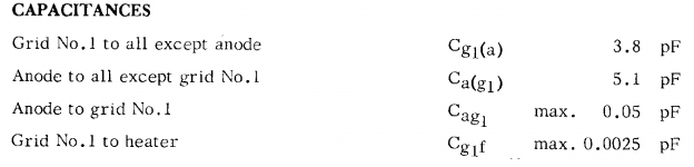
PRR, to be sure I'm not missing anything here, when you say 0.025pFd you mean regular picofarads, right? Like 0.025pF?EF86 claims 0.025pFd. 6AU6 claims 0.003pFd.
Jan
Philips EF86 datasheet gives 0.05pF.Like 0.025pF?
Attachments
- Home
- Amplifiers
- Tubes / Valves
- Advantage of beam triode over simple triode