Hello All,
Few days back I perfboarded the Threshold Sl10 PreAmp from the schematics available in this forum.
It simulated well in the LTSpice and sounded good too.
This motivated me to try the SL10 RIAA too.
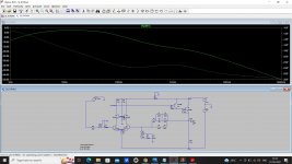
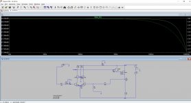
But the LTspice simulation and the perfboarded circuit both failed to show a proper response.
I used BC550C NPN and BC556B PNP BJTs.
LTSpice BC550C BJT model is that of Bob Cordell.
I didn't use the DC servo in the simulation, but used it while perfboarding the circuit.
Where am I going wrong?
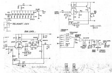
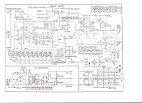
Please see the attached .asc files and the schematics I followed.
Best Regards
Few days back I perfboarded the Threshold Sl10 PreAmp from the schematics available in this forum.
It simulated well in the LTSpice and sounded good too.
This motivated me to try the SL10 RIAA too.
But the LTspice simulation and the perfboarded circuit both failed to show a proper response.
I used BC550C NPN and BC556B PNP BJTs.
LTSpice BC550C BJT model is that of Bob Cordell.
I didn't use the DC servo in the simulation, but used it while perfboarding the circuit.
Where am I going wrong?
Please see the attached .asc files and the schematics I followed.
Best Regards
Attachments
Hi Rayma,Post the predicted and measured RIAA responses here in PDF.
I don't have no means to measure the RIAA response.
By listening comparison against Hagerman Bugle 2, the sound is very rolled off in the highs area (almost no high frequency).
Bass/ Mid area seems sounding ok.
Regards
What exactly was wrong with the SL10 RIAA simulation response?
You can't really compare the Hagerman with these, since the designs are very different
and would not be expected to sound similar. Hagerman has a ~48kHz shelf.
SL10 has a ~71kHz shelf. Discrete bipolar input can interact with cartridge as well.
If you built per the schematics, one difference is the input resistors, 47k vs 100k.
Do you have these values in the circuits, and what cartridge is used?
Last edited:
Hi Rayma,What exactly was wrong with the SL10 RIAA simulation response?
You can't really compare the Hagerman with these, since the designs are very different
and would not be expected to sound similar. Hagerman has a 48kHz shelf.
If you built per the schematics, one difference is the input resistors, 47k vs 100k.
Do you have these values in the circuits, and what cartridge is used?
As I mentioned, the sound was compared with Bugle to understand the presence of frequency spectrum. And It's very obvious that the higher frequencies are just missing in case of SL10 built. The cymbals are almost absent.
Even the LTSpice simulation shows same rolloff whereas the high gain section simulation shows flat response beyond 20k.
I have used both 100k and 47k as cartridge load resistors. Hardly any difference.
My cart is Shure V15 type III.
Regards.
You should use an inverse RIAA network at the phono input, so the output response will be flat with a flat input.
Then any response deviations are very clear. Hagerman has such a circuit shown on their site. Or one is here:
http://hifisonix.com/wordpress/wp-content/uploads/2016/12/Accurate-Inverse-RIAA.pdf
Then any response deviations are very clear. Hagerman has such a circuit shown on their site. Or one is here:
http://hifisonix.com/wordpress/wp-content/uploads/2016/12/Accurate-Inverse-RIAA.pdf
To me it looks like a RIAA curve. I can't tell from the diagram how much is the deviation but it doesn't seem drastic to me.
Double check the values of resistors and capacitors you put in the circuit. R1-R6, R18. C1, C2, C5 and C7
Double check the values of resistors and capacitors you put in the circuit. R1-R6, R18. C1, C2, C5 and C7
Noted well. Will try tomorrow morning.You should use an inverse RIAA network at the phono input, so the output response will be flat with a flat input.
Then any response deviations are very clear. Hagerman has such a circuit shown on their site. Or one is here:
http://hifisonix.com/wordpress/wp-content/uploads/2016/12/Accurate-Inverse-RIAA.pdf
What actually pushed me to check the simulation was the sound response of the perfboard proto of the RIAA which was lacking high frequency response.
I checked various photographs of the original SL10 inside and at least the 2 RIAA capacitor values(4n7 & 15n) and the 475R resistors are matching with the schematics attached in the first post.
Regards
I think bhaskarcan doesn't have means to measure freq response, with or without inverse RIAA.You should use an inverse RIAA network at the phono input, so the output response will be flat with a flat input.
Then any response deviations are very clear. Hagerman has such a circuit shown on their site. Or one is here:
http://hifisonix.com/wordpress/wp-content/uploads/2016/12/Accurate-Inverse-RIAA.pdf
Hi Chip_mk,To me it looks like a RIAA curve. I can't tell from the diagram how much is the deviation but it doesn't seem drastic to me.
Double check the values of resistors and capacitors you put in the circuit. R1-R6, R18. C1, C2, C5 and C7
I also thought about the components' values first and hence made the perfboard circuit twice, double checking the values. Same result.
The simulation is showing about -14 db loss at 1khz which seems drastic.
(Though I'm not very experienced with spice sim.)
Regards
RightI think bhaskarcan doesn't have means to measure freq response, with or without inverse RIAA.
That's the way RIAA equalisation works Check thisHi Chip_mk,
I also thought about the components' values first and hence made the perfboard circuit twice, double checking the values. Same result.
The simulation is showing about -14 db loss at 1khz which seems drastic.
(Though I'm not very experienced with spice sim.)
Regards
You can alternatively use FFT software instead of anti-Riaa hardware. ARTA, REW, etc. in FR mode with the Riaa curve as microphone compensation. Tolerance as tight as math. Only thing you can't do well with such a method is testing with square waves.Right

Then he can use a square wave input to the inverse RIAA, which visually works well enoughI think bhaskarcan doesn't have means to measure freq response, with or without inverse RIAA.
for his purposes in this case.
Last edited:
You are looking at the RIAA playback curve and hearing the equalization that you see.Hi Rayma,
I don't have no means to measure the RIAA response.
By listening comparison against Hagerman Bugle 2, the sound is very rolled off in the highs area (almost no high frequency).
Bass/ Mid area seems sounding ok.
The LPs are pre-equalized to be the complement of the RIAA curve, so the playback is flat,
ever since 1948. Just like with the inverse RIAA circuit recommended.
Rayma,You are looking at the RIAA playback curve and hearing the equalization that you see.
The LPs are pre-equalized to be the complement of the RIAA curve, so the playback is flat,
ever since 1948. Just like with the inverse RIAA circuit recommended.
Yes, you are right and I missed the point before.
Thanks for you patience.
I'll use an inverse RIAA circuit schematic with the SL10 RIAA and check the response.
Meanwhile may I request if someone can please simulate the RIAA schematic attached with the first post. Thus to confirm if my sim has any error.
I have shared the .asc file of my LTSpice sim too.
Please note that the PDF schematic attached has a 475 or 470 ohm resistor missing from the feedback loop.
Best regards.
Hello Salas,You can alternatively use FFT software instead of anti-Riaa hardware. ARTA, REW, etc. in FR mode with the Riaa curve as microphone compensation. Tolerance as tight as math. Only thing you can't do well with such a method is testing with square waves.
Thank you for your suggestion.
Shall explore accordingly.
Best regards.
- Home
- Amplifiers
- Pass Labs
- Threshold SL10 RIAA