TI measurements of coil, side 14 ti userguide. Se the top end vs normal quality coils only matters under 0,01% THD.
If the coils are inadequate they also should get warm at high power to load.
Anyone has measured THD of these boards with low quality coils?
If the coils are inadequate they also should get warm at high power to load.
Anyone has measured THD of these boards with low quality coils?
Hard mode pot and relay bypass (hand iron + wick) is done. Rather proud of my tiny wire twisting. The topping flux does not clean up easily. For amp #2 I will just bypass the relay.


The bypass is easy. There is a single (diode? 0-Ohm resistor? Not sure) which sinks from the FET and runs the (stateless) relays.


Auto power-on will be trickier. I will need an ST-Link programmer.
I had some extra 5W/mK pads. I added diaper rash cream (thermal paste) as a cherry on top and underwrote my own insurance policy (Conformal coating)

The bypass is easy. There is a single (diode? 0-Ohm resistor? Not sure) which sinks from the FET and runs the (stateless) relays.
Auto power-on will be trickier. I will need an ST-Link programmer.
I had some extra 5W/mK pads. I added diaper rash cream (thermal paste) as a cherry on top and underwrote my own insurance policy (Conformal coating)
Hi that is too much thermal paste. It seems adding through hole coils is an easy job when you cut the jumper connectors and go from the PCB to the output connectors. The Aiyima A8 has normal coils (and no 2 x 1 nF).
If there are no shims between heatsink and PCB they took a risk. Mechanical force will be applied to the too close to the mounting holes soldered SMD parts if so.
If there are no shims between heatsink and PCB they took a risk. Mechanical force will be applied to the too close to the mounting holes soldered SMD parts if so.
A heatsink on an ma12070(p) is of dubious value. The chip has an "EPAD" (exposed thermal pad) on the bottom. The intent is to use the PCB itself for heat dissipation. From the datasheet, page 25, "The QFN package with exposed thermal pad at the bottom side is thermally sufficient for most applications..." It goes on to give more suggestions about the PCB design to give the best thermal performance. Another quote, page 12, "In most applications, this allows the MA12070 to run at high power levels without a heatsink." Even if you have a perfectly-mated heatsink, I can't imagine it's terribly useful, given that the top of the package is plastic.
They put incompressible spacers. The paste is just so I can get a good enough squish factor for the replacement pads to work well. I think my 1.5mm pads are only 1.5W/mK so I used a .75mm far better pad and enough non-conductive paste to eliminate air pockets. The picture might be a bit deceptive due to syringe nozzle width, parts size, and overhead photo angle. The blobs are very flat.Hi that is too much thermal paste. It seems adding through hole coils is an easy job when you cut the jumper connectors and go from the PCB to the output connectors. The Aiyima A8 has normal coils (and no 2 x 1 nF).
If there are no shims between heatsink and PCB they took a risk. Mechanical force will be applied to the too close to the mounting holes soldered SMD parts if so.
Here is a fun article on quantity: https://www.gamersnexus.net/guides/3346-thermal-paste-application-benchmark-too-much-thermal-paste
The A8 really has no caps in the output filter? Fascinating. In infineon's filter sheet they compare THD+N of ferrite beads vs LC filter and the LC seems to underperform. The rear panel of the PA3s only has a single point of retention to the main PCB.... via the rear jumper board. So any cuts there would make the connection (inductors) the physical strain member in that relationship. FOr an amp that measured quite well on ASR, it really is a bit janky. I guess that speaks very highly of the MA12070.
A heatsink on an ma12070(p) is of dubious value. The chip has an "EPAD" (exposed thermal pad) on the bottom. The intent is to use the PCB itself for heat dissipation. From the datasheet, page 25, "The QFN package with exposed thermal pad at the bottom side is thermally sufficient for most applications..." It goes on to give more suggestions about the PCB design to give the best thermal performance. Another quote, page 12, "In most applications, this allows the MA12070 to run at high power levels without a heatsink." Even if you have a perfectly-mated heatsink, I can't imagine it's terribly useful, given that the top of the package is plastic.
Yessir. However, this will depend on the board assembler. In the case of Topping, they did not deign to grace us with any sort of actual connection to the epad. I found the "Super Macro" camera feature on my phone and I have been abusing it. I do not trust my hand soldering enough to even think about smearing some chip quik in there and heating it. Micro conductive beads leaking through the epad vias and shorting a pin just seems way too likely on a prefab assembly.
Does not seem to be 100% well soldered but I also think it is just OK as the solder is at the other side of the board. One can not expect all the metallized holes to be completely filled with solder.
The heatsink-paste discussion in the link is not entirely applicable to plastic IC's. CPUs and CPU heatsinks are flat metal surfaces and even a tiny blob of paste will distribute quite well and using too much of the stuff will result in it being squeezed out. Also mounting the heatsink without any paste works quite OK in many cases (not that it should be done but still...). It has been designed quite laymen/fool proof.
In your case paste is applied to a pad that is applied to the plastic IC....possibly making heat transfer less good than just the pad.
BTW the graphs are of course about that specific LC filter with exactly those cost optimized parts. I think Infineon steers us to the ferrite beads and 2 x 1 nF solution.
Last edited:
It seems the green line in the graph is not the LC filter but the Fair-Rite: 2512065007Y6 ferrite bead solution.
The 1000/35 caps are not in the best shape and various types and various date codes are used. My A8 has fake Nichicon caps AND original ones. Sorry.
A8 has the coils and the PCB has PCB pads for adding caps at the outputs.
I still wonder why so many opamps and also coupling caps have been used.
The board deserves cleaning as the flux is aggressive.
A8 has the coils and the PCB has PCB pads for adding caps at the outputs.
I still wonder why so many opamps and also coupling caps have been used.
The board deserves cleaning as the flux is aggressive.
Last edited:

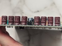
Look at the series of the 1000/35 and the font type. I have discarded the ones I had so I can’t tell anymore.
wondering PCB not ENIG?!They put incompressible spacers. The paste is just so I can get a good enough squish factor for the replacement pads to work well. I think my 1.5mm pads are only 1.5W/mK so I used a .75mm far better pad and enough non-conductive paste to eliminate air pockets. The picture might be a bit deceptive due to syringe nozzle width, parts size, and overhead photo angle. The blobs are very flat.
Here is a fun article on quantity: https://www.gamersnexus.net/guides/3346-thermal-paste-application-benchmark-too-much-thermal-paste
The A8 really has no caps in the output filter? Fascinating. In infineon's filter sheet they compare THD+N of ferrite beads vs LC filter and the LC seems to underperform. The rear panel of the PA3s only has a single point of retention to the main PCB.... via the rear jumper board. So any cuts there would make the connection (inductors) the physical strain member in that relationship. FOr an amp that measured quite well on ASR, it really is a bit janky. I guess that speaks very highly of the MA12070.
View attachment 1088500
Yessir. However, this will depend on the board assembler. In the case of Topping, they did not deign to grace us with any sort of actual connection to the epad. I found the "Super Macro" camera feature on my phone and I have been abusing it. I do not trust my hand soldering enough to even think about smearing some chip quik in there and heating it. Micro conductive beads leaking through the epad vias and shorting a pin just seems way too likely on a prefab assembly.
View attachment 1088503
JP
It seems the green line in the graph is not the LC filter but the Fair-Rite: 2512065007Y6 ferrite bead solution.
I think the bulged one might be a good candidate 😆I have no idea which are counterfeit.
Mmm, the sweep is pictured by 3 colored lines though. They could have made it easier 🙂 IME the ferrite beads and 2 x 1 nF are OK even with longer cables.
Yes I also think those 3 caps are fake. Mine had 2 series, original and fake and different date codes. All were black with white lettering. The oldest seemed original and were placed in the second row closer to the IC. Apparently parts are harder to source even for Chinese manufacturers.
For people wanting an A8, I still have an original/unmodified one in box. Send me a PM if you want it (EU only). I'll include Panasonic FC 1800/35 caps with it just in case. Despite this inconvenience the A8 sounds very OK.
Last edited:
Not sure what you are asking. Are you referring to the MA12070P needing two CLK's (BCLK on pin 21 and MCLK on pin 32)?One question using MA12070: do I need to CLK´s?
JP
sorry guys, asked my question by myself: setting MA12070 in Master Mode so CLKM/S high to VDD.
JP
JP
- Home
- Amplifiers
- Class D
- Infineon MA12070 Class D