if there is any series reistance in filtering (CRC) you can use that R for observing Iq - it's perfectly viable from moment when caps are initially filled
or you can buy cheapest Uni-T DC Clamp Ameter, it works as charm
just 10yrs ago, that was costing arm and leg
or you can buy cheapest Uni-T DC Clamp Ameter, it works as charm
just 10yrs ago, that was costing arm and leg

I have a R0 SissySIT that I may move to a lower social class. I like simple - easy to understand, easy to fix, and less to go wrong. And I don't need the gain and noise of the transformer front end anyway.
The amp has no bias issues so I believe the THF-51S that I have do not have any gate leakage issues.
I like Redneck designs. Thanks, ZM. 🙂
The amp has no bias issues so I believe the THF-51S that I have do not have any gate leakage issues.
I like Redneck designs. Thanks, ZM. 🙂
Thanks for linking my pics.I am curious, how do you measure Id in your setup? Do you have a current sense resistor in circuit somewhere?
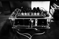
I like the B&W glamour shots of the SITs 🙂
In init version, I used 2 current sense resistor to find Vgs of SIT and P-Mos ( short GND and OUT). After that, I selected LED as SIT require and bypassed Rsense. In the last, changing Vgs of P-Mos to adjust offset.
.....
I like Redneck designs. Thanks, ZM. 🙂
that's why I posted it, in first place
I find that getting simplest solution, often is hardest to achieve - at least to my brain

Damping factor: I think it is enough without any feedback.
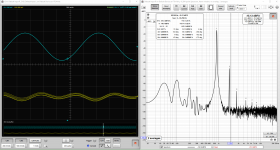
THD: 0.0073% lowest , but I prefer 0.04% ...
Hum at 100Hz: -85dB although I put 180kuF > .094R > 180kuF and the 'T' applied to correct wiring ground, BA-3 also setup under -110dB. Maybe the issue come from my PS board.
Thanks for everything, PaPa and ZenMod.
THD: 0.0073% lowest , but I prefer 0.04% ...
Hum at 100Hz: -85dB although I put 180kuF > .094R > 180kuF and the 'T' applied to correct wiring ground, BA-3 also setup under -110dB. Maybe the issue come from my PS board.
Thanks for everything, PaPa and ZenMod.
Attachments
Last edited:
Wow, that is a lot of capacitance in your power supply. But hum can still happen with lots of capacitance. Component placement and wire routing and wiring arrangement can cause hum, or minimize hum, depending on how it is done.
What is the output voltage/power/load for your distortion measurements?
What is the output voltage/power/load for your distortion measurements?
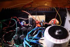
yeah, few better pics than shown in post #78 could help
what I can see there - first impression is that in general - wire gauge is too thin
that, combined with possible critical wiring, can explain excessive ripple on output
though, don't forget that SIT isn't much better than power resistor of moderate ohmic value, when speaking about rail ripple rejection
I find that I can get a better understanding of a circuit if I sim and play around with parameters. So the Redneck ZM DEFISIT went into LTSpice this morning and after a little while I think I understand it. It is so simple that it is brilliant. Just some voltages and voltage dividers to get the job done.
In the simulation I just used whatever LEDs that gave the correct voltage drop. In real life I will test some LEDs at 0.5mA before putting them into the circuit.
Hopefully my THF-51S, heatsinks, and AC power will behave and the build will be a success. Now to rummage through my parts box and determine what I need to buy. Hopefully I can keep it local. I checked the local electronics shop's website and they appear to have some LM385-1.2 voltage references which start at 15uA.
Attachments

..... It is so simple that it is brilliant
.....
no big deal ....... as we know, brilliant is ZM's nature

Wow, that is a lot of capacitance in your power supply. But hum can still happen with lots of capacitance. Component placement and wire routing and wiring arrangement can cause hum, or minimize hum, depending on how it is done.
ya, I said something wrong yesterday, total I have 320kuF, in PS: 80kuF > .093R >80kuF per rail. I used 16AWG wire for all high current circuits. Is it need to change something more?yeah, few better pics than shown in post #78 could help
what I can see there - first impression is that in general - wire gauge is too thin
that, combined with possible critical wiring, can explain excessive ripple on output
though, don't forget that SIT isn't much better than power resistor of moderate ohmic value, when speaking about rail ripple rejection
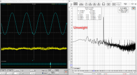
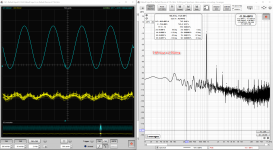
all results are performed at 8Vrms in output w/o load. Distortion can get lower as mentioned in article BA-3 from NP.What is the output voltage/power/load for your distortion measurements?
I forgot to connect load before getting measurements ~~.
Anyway, I will adjust THD on weekend, maybe I need to decrease distortion to 0.02%. I will update it again.
Last edited:
............. Distortion can get lower as mentioned in article BA-3 from NP.
I forgot to connect load before getting measurements ~~.
Anyway, I will adjust THD on weekend, maybe I need to decrease distortion to 0.02%. I will update it again.
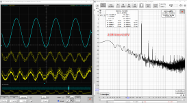
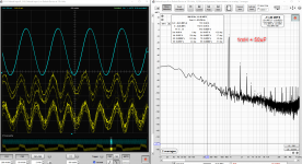
You may end up with the third harmonic dominating if you can get the distortion down to that level at 1W/8R.
Me, I prefer the second harmonic dominating. 🙂
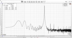
My lowest THD w H2neg 🤓: 7.5R 0.1% >> 5R 0.15% >> 2.5R 0.35%
For Vout: 2.75Vrms >>2.73Vrms>>2.67Vrms : so maybe that output impedance's around ~0.08 df=100 ? 🤔
For Vout: 2.75Vrms >>2.73Vrms>>2.67Vrms : so maybe that output impedance's around ~0.08 df=100 ? 🤔
Attachments

Last edited:
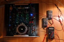
I just startup amp again to check volt drop at 0.094R CRC , after 3min 0.356V . That's mean total 3.78A and ~1.89A for each CH.
Oh, I well noted your warning 🙂 so I moved transformer from F7 to RN and DC is 22V5 per rail.
Oh, I well noted your warning 🙂 so I moved transformer from F7 to RN and DC is 22V5 per rail.
Last edited:
Looking at the pictures (post #78) there appears to be a copper plate between the output devices and the heatsink. I don't know whether that helps or hinders, but the negative aspect is that it adds another interface layer for heat transfer.
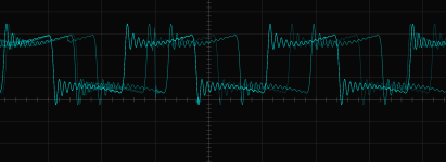
Looking at the distortion plots and oscilloscope waveforms in post #93, I see that the blue oscilloscope trace is about 4 divisions peak to peak, 200mV per division, for about 800mV peak to peak. Was this an 8Vp-p signal measured with a X10 probe and the oscilloscope set for X1? I assume this was the amplifier output signal.
The 0.10% THD at 7.5R is quite good. Could that be due to choice of Mosfet? I know that my SissySit with THF-51S and IRFP 9240 was around 0.26% THD at 8R. However I don't know how much the input buffer and transformer contributed to the THD, if much at all.
I'm not sure, maybe it come from Bergquistwhat you're using as thermal pad for mosfet?
Actually, It helps to spread heat more evenly and copper conducts heat faster than aluminum. I can touch around FET zone ya, I guess ~50'C.I don't know whether that helps or hinders, but the negative aspect is that it adds another interface layer for heat transfer.
Looking at the distortion plots and oscilloscope waveforms in post #93, I see that the blue oscilloscope trace is about 4 divisions peak to peak, 200mV per division, for about 800mV peak to peak. Was this an 8Vp-p signal measured with a X10 probe and the oscilloscope set for X1? I assume this was the amplifier output signal.
The 0.10% THD at 7.5R is quite good. Could that be due to choice of Mosfet? I know that my SissySit with THF-51S and IRFP 9240 was around 0.26% THD at 8R. However I don't know how much the input buffer and transformer contributed to the THD, if much at all.
My measurement directly connect to interface Scarlett 2i2 at binding posts. I didn't calib Vac... , just FFT check.
I could not find the good P-FET as 9140 or Harris FET. I luckly bought Toshi FET 20$ for 2pair used.
I think 16R can bring more lower distortion, mean bass zone will be clear , in low impedent zone have much harmonic.
Last edited:
Sissy becomes a Redneck:
So I decided to convert my SissySIT to a Redneck.
But before I made the life changing decision to my SissySIT, I cooked the SissySIT for about one and a half hours to make sure that the THF-51Ss were stable. The ambient temperature was about 24 degrees C and the heat sinks were at about 53 degrees C. This was at the outside face of the base of the heat sink, directly opposite the THF-51S and IRFP9240. The Vgs of the THF-51S of both channels were stable at -2.99V left and -2.90V right.
As with many of my latest projects, this was done on strip board. I used parts from by spare parts box as much as possible, so I substituted parts with different values where I thought I could. I did some LTSpice simulations to see if it was possible, and then did some testing of the finished board to confirm. I also used LTSpice to help me lay out the components on the board. I find it very handy as I can move components around until I am happy with the layout. I can then run a simulation to make sure that the circuit and wiring are correct.
I also tested some 3mm LEDs to find their voltages before putting them on the board. I tested them at a current of approximately 470mA, which is about the current that they would operate in the circuit. Voltages were: red 1.57V, green 1.78V, blue 2.51V. For the 6.5V that was required for the circuit, I used three red and one green together.
For the first power-up I tested without the IFFP9240 and THF-51S installed. Trimmer P1 was set at 0R and P2 was set a 0R relative to the IRFP9240 gate. I powered up with a Dim Bulb Tester (DBT) in place and confirmed that the voltage reference was at 2.5V (2.46V measured) and the LED string was at 6.5V (6.6V measured). So far so good, so then the output devices were installed, meters attached, DBT in place, and I powered up again. No surprises so I made the adjustments to set Iq and output offset.
I slowly increased Iq over a period of time and left it at 1.7A. The bias and Iq were stable. That was last night. This morning I turned it on and after two and a half hours it was at 1.66A. The ambient temperature this morning was probably cooler so that was probably why the current was lower.
I did a FFT measurement at 1W and the results were about the same as when it was a SissySIT channel. I also did a stepped analysis to check the frequency response, and it confirmed the LTSpice simulation results that showed no frequency response loss, as I was concern with my substitution of 100uF in place of 470uF in the signal path to the THF-51S gate. The 100uF caps were Nichicon Audio Grade that I had in my parts box.
I haven't done any listening tests yet but I think it should sound just like the SissySIT, except without the gain of the input transformer. My preamp has enough gain so that will not be an issue.
Power-on speaker output offset seemed to be a bit over +3V or so, decreasing to less than 1V in about 15 seconds. The SissySIT power-on speaker offset seemed to be a bit over +2V or so, and dropped below 1V quickly.
Now to build the other channel.
Attachments
-
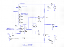 Redneck Defisit - As-built.png18.6 KB · Views: 121
 -
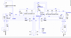 Redneck DEFISIT Layout.png26.8 KB · Views: 119
 -
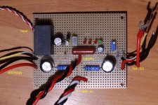 Redneck DEFISIT Board Top.jpg620.2 KB · Views: 104
 -
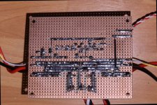 Redneck DEFISIT Board bottom.jpg646.6 KB · Views: 104
 -
 Redneck DEFISIT Right Channel - testing.jpg515.8 KB · Views: 108
 -
 Redneck DEFISIT Right Channel-offset, Iq@0.1R, THD-51S Vgs.jpg384.4 KB · Views: 122

- Home
- Amplifiers
- Pass Labs
- Redneck ZM DEFiSIT/DEF biasing