I said I wasn't going to going to do it but I did it anyways. That's diy.
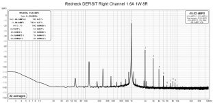
So I changed the CRC power supply filter to CLC, from 44mF-0.1R-44mF to 44mF-Hammond 156B-44mF. The 156B is 1.5mF@5A, 0.07R, 400V max.
Now there is no audible hum with my ear against the speaker.
The 120 Hz noise dropped about 20dB, and the harmonics of 120 Hz and also the intermodulation distortion also dropped considerably.
Before and after FFT:
Attachments

Looks good as an improvement!
2 156Bs per channel, because +/- rails or because balanced? Thanks in advance for answering a Luddite question.
2 156Bs per channel, because +/- rails or because balanced? Thanks in advance for answering a Luddite question.
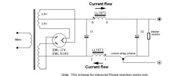
can be put only ones L on common 0v gnd in a +V 0 -V? look like isn't taboo (forget the double coil of LL)
Attachments
wow great !! @Ben Mah you almost got near end point.
If you have time, can you let me some lesson learn: bypass either chokes for rail PS or replace 0.1R to observe behavior of SIT ? I think it can reduce more if we just make smooth for one of the two rail
By the way, I did some contest with F5 turbo 32V J/K1530 from my friend. My DEF is lack detail in high-freq and low-Freq jump up when operated ~ especially in high power . I see your picture , it maybe get same issue.
Attachments

Last edited:
khoasonphong, I would have to take apart my ampllifier to bypass the PS chokes, so no, I will not be doing that. This is diy (do it yourself) so perhaps you can do that in your amplifier.
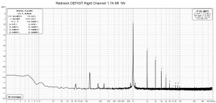
Looking at your FFT plot and comparing it to my plots with CRC and CLC supplies, your FFT showed the noise floor at a minimum at about 20kHz and then rose as the frequency decreased. My FFT plots showed near constant noise floor until about about 20Hz, and then rose as the frequency decreased. So the noise floor in my amplifier rose a bit in the non-audible range whereas the noise floor in your amplifier was rising in the audible range. Now in my case I do not know whether the noise floor rising below 20Hz was due to the limits of the test setup or was the actual amplifier performance. But I think that is a moot point since it was at such low frequencies and at a frequencies that my speaker cannot reproduce.
Looking at your FFT plot I would say that perhaps the high noise was due to your amplifier construction or perhaps it was due to your test setup, or perhaps it was a combination of both. You also noted "2.5R" on your plot so I assumed you loaded the amplifier output with 2.5 Ohms. For my tests I loaded my amplifier with 8 Ohms. I also set the FFT analysis to 32 averages whereas yours was set to 2 averages. For a more exact comparison, conditions should be as identical as possible.
Without knowing the details of your amplifier or your test setup, it is difficult to assess your results. You mentioned in post #85 that you have 180mF - 0.094R - 180mF in your power supply. My CRC was 44mF - 0.1R - 44mF. So you should be able to achieve the same results that I achieved with my CRC supply.
As to your comparison with a F5 Turbo, the F5 Turbo has much more power, so the results depend greatly on the rest of the system, especially the speaker's sensitivity.
I can say though that my amplifier does not lack in high or low frequencies, and with my sensitive speakers I think the amplifier sounds great. 🙂
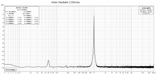
So I was curious about the low frequency measurements of my FFT setup. It comprises a Focusrite 2i2 second generation, an older Victor 1kHz oscillator on AC power, and a diy switchable attenuator (Dan Joffre/Akitika design), and a Lenovo laptop. For the Redneck Defisit FFT I also inserted an ACP+ preamp after the Victor oscillator to amplify the 2.53Vrms maximum output to 2.83Vrms for 1W at 8R.
Testing the oscillator on its own, the noise floor rose about 8dB at the low frequencies. Testing the oscillator and amplifier together (no ACP+), the noise floor rose about 16dB at the low frequencies.
So each component added to the "measured" low frequency noise. I have no idea what happens within the FFT analysis process so I do not know whether the contribution is from each component or from the process itself. But the "measured" noise below 20Hz is not something I worry about. 🙂
Attachments

I'm thinking this redneck DEF thingy is my next SIT experiment... getting bored with the TDV/SITfo.
Besides I like the name. 😏
Is this the proper method of measuring Ugs of SIT?... I know the P-MOS method works.
Cinco does love simple. More time to sit back and listen.

Besides I like the name. 😏
Is this the proper method of measuring Ugs of SIT?... I know the P-MOS method works.
Cinco does love simple. More time to sit back and listen.

Ok, here's my revised Ugs testing for the devices. Now I have the numbers for these spice models to fiddle with the sims.
20V at 2A makes the math easy, 40W dissipation and device looks like a 10 ohm resistor.
P = I*E = (2A)*(20V) = 40W
R = E/I = (20V)/(2A) = 10ohms
I'll probably test for a few different PS voltages and currents on the real devices. Say 18V, 20V, 22V at 1.8A and 2A.

20V at 2A makes the math easy, 40W dissipation and device looks like a 10 ohm resistor.
P = I*E = (2A)*(20V) = 40W
R = E/I = (20V)/(2A) = 10ohms
I'll probably test for a few different PS voltages and currents on the real devices. Say 18V, 20V, 22V at 1.8A and 2A.
- Home
- Amplifiers
- Pass Labs
- Redneck ZM DEFiSIT/DEF biasing