yes, it is having 50R with 1K resistor shorted
now, I told you to not mess with (pot) things you don't understand fully ....
look where it got me ......... lost for good
now, I told you to not mess with (pot) things you don't understand fully ....
look where it got me ......... lost for good
This is how I learn, messin with stuff. Besides you were too slow to warn me 🤣 and anyway having that pot temporarily destroying the DC offset didn't kill my little 4" Fostex speaker or my preciousss Japanese SIT so no harm done. Except I did by accident hook up my B1 buffer to both rails of my bench supply, instead of to the positive rail and to ground, and I apparently fried the indicator LED and some of the insulation on the output wires in the process. But the B1 is still working in my main system now so, haha.yes, it is having 50R with 1K resistor shorted
now, I told you to not mess with (pot) things you don't understand fully ....
look where it got me ......... lost for good
Funny enough, I then tried yr SIT amp + autoformer with a truly passive preamp, just a dumb pot (Schiit SYS) in front of an antique Sony CD player, a CDP-302, and it sounds even moar fantastic than with the little trashy bluetooth adapter I was using as a source. I really want to build this 'redneck' SIT thing now. You'll probably be mad because I'm going to use those trashy salvaged heat sinks you told me were too smol, but I did dial down the bias from 2A to 1.4A and it sounded fine to me, so it won't be a complete inferno. The IRFP got to over 60C but those devices can take it and I have yet to burn one out. I just need to source a PS and figure out a chassis now. Maybe I'll bug @rhthatcher


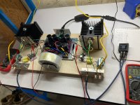
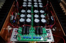
So I built this thing in stereo, in a 4U Deluxe chassis, and borrowing a PSU from an Aleph 30.
It plays music, but there is massive hum if the inputs are open, less hum if there's a source attached, and nearly no hum if the inputs are shorted. So the first winding on the little Edcor input trafos are picking up mains noise somehow (see ZM's diagram, below), or something else, or I did something wrong. I tried moving wires around (e.g. separating wires I had twisted together originally), no effect. The only thing I can think of is to make little copper shields for the Edcor windings, ground them, & see if the noise goes away. There's enough of an air gap between the Edcor coils and the laminates that I could fit something in there. Thoughts, suggestions?
The other thing I dislike is that the DC offset spikes at turn-on to ~2V and bleeds down to tens of mV as the machine warms up. Since the current through the sense resistor is minimal on startup, maybe this is okay, but it makes me leery of moving this amp to my main system without a speaker protector circuit on it, which I haven't built yet. I really don't want to damage my main speakers in any way.
The third thing? This bracket strategy doesn't conduct heat very well. The top side of this bracket gets quite hot, and is hotter than the heat sink it's attached to. I'm not sure a sufficient amount of heat is getting to the heat sinks.
Attachments

loose bracket, mount SIT directly on heatsink
wiring to Edcors is too long and loose; try coax from input to Edcor, neat GND wiring is paramount ; everything counts when you have magnetic device in play
again - use coax everywhere or tightly twisted pairs
now, initial DC offset is really matter of parts you end with; with some other combo of SIT Ugs value, behavior can be both less and ore critical, depending of your luck
dunno did you use exact parts values I did show in opening of thread, but I didn't had too critical powering up behavior with that schmtc and OS parts I had in tests ...... pretty much everything covered in post #9
loose bracket, mount SIT directly on heatsink
Trying not to tap & drill a UMS heat sink, but I hear you. the 44mm spacing hole-to-hole of the Tokins is irritating, hence the bracket, but now I know it's inadequate for long term use, thankfully long before I burned out an obsolete and practically irreplaceable device. Also these ceramic insulators I have for my SITs are fragile, single-use items only- I've broken three so far on disassembly. Idk what the alternatives are.
wiring to Edcors is too long and loose; try coax from input to Edcor, neat GND wiring is paramount ; everything counts when you have magnetic device in play
again - use coax everywhere or tightly twisted pairs
ok. I have to find some coax then, to go with my new sheets of keratherm, gah this stuff isn't for sissies
Idk. I built & ran the mono channels on my bench supply, which uses giant antique salvaged capacitors at many volts below their spec, and saw DC offsets that did not alarm (also no gosh-darn hum). It was only when I moved those exact, unmodified amp channels to the fine little "new original F5 power supply" clone that was in my Aleph 30 that I noticed a prolonged period of high DC offsets. Also the hum. So I let everything sit in my garage for a week before I jumped to conclusions. But I didn't systematically test things & so I have no alternative hypotheses to present.now, initial DC offset is really matter of parts you end with; with some other combo of SIT Ugs value, behavior can be both less and ore critical, depending of your luck
dunno did you use exact parts values I did show in opening of thread, but I didn't had too critical powering up behavior with that schmtc and OS parts I had in tests ...... pretty much everything covered in post #9
A resurrection of sorts
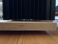
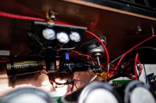
Let this one sit awhile. Gave up on the thin brackets mounting the SITs to heat sinks & on a chassis with lord knows how many ground loops. Decided the 'test bed' approach was worth a shot, still using the dual rail PSU borrowed from my Aleph 30 build. One of my ceramic insulators for the THF-51S cracked so I hacked something for one channel out of keratherm sheets & mounted them back on the monoblock-style MoFo heatsinks I'd tapped for this purpose.
This PSU swings 42.2V rail to rail. It was pretty easy to dial in a bias of 1.8A measured across a 0R1 resistor on the MOSFET drain, with DC offsets of <20mV, so I called it good. I certainly can't hear distortion well enough on my bench to attempt further tweaks of that kind by ear. For the curious, this worked out to SIT and MOSFET Vgs of Lch: -2.988V, -4.64V; Rch: -3.005V, -4.688V. There is not much hum now, either on the bench or when talking through a proper preamp to decent speakers. No ground loops through plywood, haha.
Since I've been listening lately to a current source amp on 2-ways wired with a series passive crossover, I decided to treat this amp like it was a current source, that is, I made no changes whatsoever to my crossovers. It sounds okay! Maybe a little less bass and a little less treble than my weird clone of the F1J, but with the Edcor trafos in the signal path of this SIT amp giving some modicum of voltage gain I'm not ready to lay blame on the actives for narrow bandwidth. One thing is clear, I really need a clean preamp with gain to evaluate amps like this properly. With my B1 buffer cranked to 11 I still am lacking volume. I have no idea how close I am to clipping this thing, nor what it might sound like on the way there.
That said, listening to CDs like Beck, RHCP and Smashing Pumpkins, there is a lot of atmosphere and placement to the instruments. Is this the SIT soundstage effect? If I could get the top & bottom end I've gotten used to with this kind of imaging and depth, I'd be stoked.
NB, this style of heat sink is inadequate for this application, I can't recommend them here. They're rated 0.40degC/W, and they're measuring 65C as I type after less than an hour of play. Way too hot to even touch for a split second.
Attachments
you just need proper Cojones to drive that Edcor + OS
be sure that your B1 is set for minimum possible Rout, meaning no series protecting resistor in output line of it
if in doubt, post schm of your B1
elevate those sinks from base, at least 3", it'll do wonders
and, you can put small 8cm fan under each, light breeze will shave at least 10C
be sure that your B1 is set for minimum possible Rout, meaning no series protecting resistor in output line of it
if in doubt, post schm of your B1
elevate those sinks from base, at least 3", it'll do wonders
and, you can put small 8cm fan under each, light breeze will shave at least 10C
you can sell to me the heatsink .....A resurrection of sorts
Let this one sit awhile. Gave up on the thin brackets mounting the SITs to heat sinks & on a chassis with lord knows how many ground loops. Decided the 'test bed' approach was worth a shot, still using the dual rail PSU borrowed from my Aleph 30 build. One of my ceramic insulators for the THF-51S cracked so I hacked something for one channel out of keratherm sheets & mounted them back on the monoblock-style MoFo heatsinks I'd tapped for this purpose.
This PSU swings 42.2V rail to rail. It was pretty easy to dial in a bias of 1.8A measured across a 0R1 resistor on the MOSFET drain, with DC offsets of <20mV, so I called it good. I certainly can't hear distortion well enough on my bench to attempt further tweaks of that kind by ear. For the curious, this worked out to SIT and MOSFET Vgs of Lch: -2.988V, -4.64V; Rch: -3.005V, -4.688V. There is not much hum now, either on the bench or when talking through a proper preamp to decent speakers. No ground loops through plywood, haha.
Since I've been listening lately to a current source amp on 2-ways wired with a series passive crossover, I decided to treat this amp like it was a current source, that is, I made no changes whatsoever to my crossovers. It sounds okay! Maybe a little less bass and a little less treble than my weird clone of the F1J, but with the Edcor trafos in the signal path of this SIT amp giving some modicum of voltage gain I'm not ready to lay blame on the actives for narrow bandwidth. One thing is clear, I really need a clean preamp with gain to evaluate amps like this properly. With my B1 buffer cranked to 11 I still am lacking volume. I have no idea how close I am to clipping this thing, nor what it might sound like on the way there.
That said, listening to CDs like Beck, RHCP and Smashing Pumpkins, there is a lot of atmosphere and placement to the instruments. Is this the SIT soundstage effect? If I could get the top & bottom end I've gotten used to with this kind of imaging and depth, I'd be stoked.
NB, this style of heat sink is inadequate for this application, I can't recommend them here. They're rated 0.40degC/W, and they're measuring 65C as I type after less than an hour of play. Way too hot to even touch for a split second.
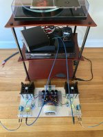
The heatsinks were ~$70 each on Newark a year or so ago, plus shipping to US destinations. I drilled and tapped this pair for M4 thread.
It wasn't possible to see in the first photos, but there is an air gap of about half a centimeter between the wood and the base of the heat sinks from a triad of furniture-style felt pads. It's not much but not nuthin either. Thinking about little fans to mount on top or bottom to blow through the fins, but the vertical mounting bolts are in the way.just increase the clearance for at least 3"
then, if needed, mount fans
Attachments
I said - increase clearance for 3" minimum
I did saw clearance of 5mm, and that's practically nothing, for that type of heatsink
or - open holes for fans in plywood base, mount them (fan flush with plywood) , and in that case you only need about 20-30mm clearance between plywood base and floor/shelf
I did saw clearance of 5mm, and that's practically nothing, for that type of heatsink
or - open holes for fans in plywood base, mount them (fan flush with plywood) , and in that case you only need about 20-30mm clearance between plywood base and floor/shelf
I got curious about the input load characteristics of this amplifier. The inductance across the RCA input jack is 0.58-0.59mH. The DC resistance is 55.4 ohms. Viewed as an RL high-pass filter these values would start rolling off below ~15kHz. No wonder the bass was soft.
Yes, thank you ZM for the suggestion to eliminate the series output resistors in my B1 buffer up front of this amp. Assuming that would give it the current it wants, would it help what I'm interpreting as a wicked-high reactance to low frequency input?
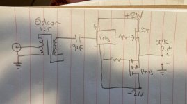
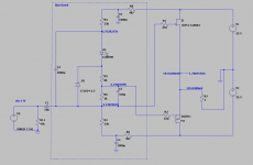
Simplified schematic as built, shown below.
Yes, thank you ZM for the suggestion to eliminate the series output resistors in my B1 buffer up front of this amp. Assuming that would give it the current it wants, would it help what I'm interpreting as a wicked-high reactance to low frequency input?
Simplified schematic as built, shown below.
Attachments
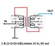
ignore Rdc of autoformer..... it is important figure but it's having nothing with things you need to take care of here
think of impedance of OS input node, then divided by autoformer transfer ratio
roughly - resistance from gates voltage generator to upper rail, in parallel with resistance from gates voltage generator to lower rail; then divide that with 4^2 (autoformer voltage transfer ratio squared, to get autoformer impedance transfer ratio)
see pic in post #1; so, say that you have 43K up and 36K down; that's aroundish 19K6
divide that with 16
you get that 1K22 is Rin of entire shebang
all that ignoring possible current demands of SIT gate, counting on sheer luck of us Greenhorns
so, whatever is in front, it must be able to drive 1220R properly
in my book anything having more than 50R of Rout is no-go
Ok, yes thank you. I didn't understand before that the resistances to rail are considered to load the autoformer, or that they are in fact parallel. I think the turns ratio here is 1:5, so 19k6 // 25 = 784 ohms reflected to primary, which is even worse. The best I think a B1 could output is about 50 ohms if I remove the output series resistors. I'll think on that.
Attachments
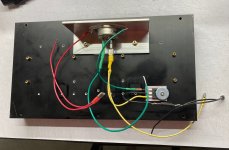
Hello ZM,
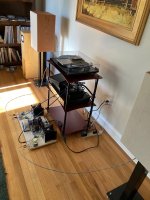
Just share my progress. The first impression is that the sound is extremely brilliant, very amazing 😱
For measurement, I will show it soon.
Just share my progress. The first impression is that the sound is extremely brilliant, very amazing 😱
For measurement, I will show it soon.
Attachments


I am curious, how do you measure Id in your setup? Do you have a current sense resistor in circuit somewhere?Just share my progress. The first impression is that the sound is extremely brilliant, very amazing 😱
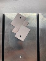
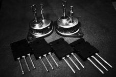
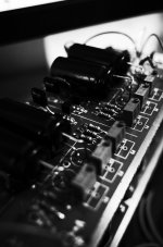
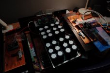
I like the B&W glamour shots of the SITs 🙂
- Home
- Amplifiers
- Pass Labs
- Redneck ZM DEFiSIT/DEF biasing