
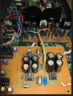
The cans are not touching the trafos, they are suspended above using a washer spacer. The trafos are insulated top and bottom with rubber gaskets and the threwbolt doesn't touch the trafos. But I will look into isolating further.
Here is one trick for shielding from orronoco.blogspot.com


In principle, it was discovered a long time ago that a field is created above chips. And it forms a cloud of electrons, a kind of micro-cold plasma, let's call it that.
Especially over plastic and ceramic ones, metal ones isolated the phenomenon, like for example processors in PCs.
I have no idea how much this changes the sound.
http://www.dddac.de/pcm63/DAC_I-V_Resistor.htmAnd maybe more important all of theese dac chips "prefer" more lower value of Riv. Someone long time ago measured distortion and current values, cant find the link in the forum 🙁
This is true for the PCM63 and passive I/V. For the AD1865, significantly larger resistors can be used. I don't know about AD1862 and the others.
Last edited:
🤔Here is one trick for shielding from orronoco.blogspot.com
View attachment 1084011
View attachment 1084012
In principle, it was discovered a long time ago that a field is created above chips. And it forms a cloud of electrons, a kind of micro-cold plasma, let's call it that.
Especially over plastic and ceramic ones, metal ones isolated the phenomenon, like for example processors in PCs.
I have no idea how much this changes the sound.
AD1865 and AD1862 have the same output current of +/-1mA, slightly different impedances, but both could work with 47R Riv. In ideal conditions, the Riv should be 0R, but the passive stage cannot achieve that, so you should go with the lowest possible Riv and normally adjust the next gain stage to that Riv.http://www.dddac.de/pcm63/DAC_I-V_Resistor.htm
This is true for the PCM63 and passive I/V. For the AD1865, significantly larger resistors can be used. I don't know about AD1862 and the others.
And as for the PCM63 itself, the Riv can be below 25R and a good low-noise gain stage after that.
Last edited:
Those figures do make CFBs look good. But from my reading of DSs, CFB's primary weakness is the current noise at the -ve input. Its typically 20pA/rtHz and when a 1k FB resistor is used this turns into 20nV/rtHz which is TL071 territory, noise-wise.
http://www.dddac.de/pcm63/DAC_I-V_Resistor.htm
This is true for the PCM63 and passive I/V.
"Here we have a good compromise between low distortion (-55dB), high headroom and Output voltage of 130mV effective."
So we buy DAC chips with -100dB THD, then trim MSB to lower H3 even further.
And then we use a 100R passive resistor to get -55dB THD.
And make it even higher with a high-gain amplifier.
Must be plenty of distortion lovers around. 😀
Patrick
from the same articleThose figures do make CFBs look good. But from my reading of DSs, CFB's primary weakness is the current noise at the -ve input. Its typically 20pA/rtHz and when a 1k FB resistor is used this turns into 20nV/rtHz which is TL071 territory, noise-wise.
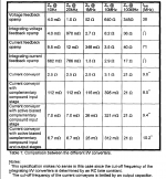
1.2 I/V Converter Requirements
It is obvious from figure I that it is important that the Iout output actually is kept at
ground potential. If Zi not the following IN converter is not zero, then the resulting
output current will not have the correct value. Of course, a small static value will not
have the same effect on signal quality as a Zin that is code/frequency dependent,
The I/V converter should fulfill the following requirements:
· Zin should be as Iowas possible.
· Zin ,should be constant not only in the audio band, but up to frequencies where the
DAC output current no longer has any significant spectral content. Remember
that the DAC output current is staircase-shaped with the steps separated by a
sample interval, and most multibit converters use oversampling filters. In other
words, the I/V converter must be able to handle the significant high frequency
content of the DAC output current without creating any audible artifacts.
I don't know if you tried the AD811 you refer to, I did a long time ago with the TDA1541 and PCM1702 according to the article by Walt Jung.
Then I was delighted with the sound compared to the classic VFA op.amp. however soon after that I switched to tubes and never went back to op.amps. Now I will put AD811 again for I/V just to compare with tubes. The difference is that now I have 3 pieces of PCM1702 that give 7.2mA p-p and a much better power supply (regulator) than then.
At that time, I also made a couple of public presentations of the I/V stage with the AD811, which I installed in my old Rotel RCD951, the reactions were very positive and everyone was delighted with the sound.
Attachments
I don't know if you tried the AD811 you refer to, I did a long time ago with the TDA1541 and PCM1702 according to the article by Walt Jung.
Yes I have tried it, as far as simple opamp I/V goes it was the best sounding part to my ears. However CFBs have another drawback, in addition to their noise and that's inflexibility in choice of Rfb. The feedback resistor cannot be decreased below the DS minimum for fear of instability. Which makes them increasingly less useful in cases where DACs are paralleled to deliver more current. Unless the designer is willing to accept higher than standard output levels.
I have tried AD811 (based on W.J. article).
https://cfas.waltjung.org/High_Performance_Audio_Stages_Using_TransZ_Amps.pdf
And it was maybe the best OP IV stage...
But that heatsink he recommended, Aavid #5801, was really insufficient and for my op. it was too hot.
https://info.boydcorp.com/hubfs/Thermal/Air-Cooling/Boyd-Board-Level-Cooling-Slide-On-5801.pdf
I didnd have at the moment bigger heat-sink so I lowered PS to +-12V. To decrease power consumption.
And it was OK but with heatsink for DIP8 package.
.
@grunf I saw that You are using AD811 without any heatsink? What power supply value are to the OP?
Last edited:
The AD811 isn't characterized at +/-7V but interpolating by eye between 5 and 15V supplies suggests the 3rd harmonic distortion will be at least 10dB lower at 15V than at 7V. 2nd harmonic will reduce too, but less dramatically.
- Home
- Source & Line
- Digital Line Level
- DAC AD1862: Almost THT, I2S input, NOS, R-2R