Congrats, Minek, good amp.
My one concern is that you have 15 devices plus IC, and the idea of the IC is to reduce the semi count.
Still, it's small, cheap devices, so it's inexpensive to build. The IC has fantastic offset control, and the two pole compensation with the Rusky trick gives high stability and strong bass. You can pick up more headroom by using double bootstraps on the VAS stage and drivers, as SteveEU mentioned.
Good design!
Hugh

Did you do the calculation of the Bushe coil?has been built (1 channel so far). Works like a champ.
I don't see it on the schematic or on the board.
Bushe Coil?? Google doesn't return anything for this term.
I guess that's the output inductor (Thiele) ?
I have one in the PSU box (below the amp in the photos, with the VU meters), together with speaker protection board.
BTW, my final build of this amp uses TL071, not LT1056 like in the sim.
In real build TL071's stability was rock solid, while LT1056 had its issues..
Last edited:
here it is, see attachmentBushe Coil?? Google doesn't return anything for this term.
I guess that's the output inductor (Thiele) ?
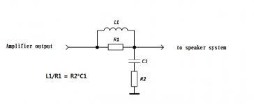
and further selection of the coil for the capacitive load of the acoustic system
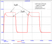
If you have an amplifier in class AB and with NFB, then without this coil you have problems with the transient response, because the impedance of the speaker system is uneven and in areas with a capacitive load it will "ring" ...
Attachments
Last edited:
Yes, I have it, physically located in the PSU box, on the same board with speaker protection.
Recently I started a thread "Fake TIP2955 from Mouser?"
where I shared my experience with fake (or defective ?) TIP2955 transistors.
Why anybody would be using TIP3055/2955 in 21st century, for an audio amp?
While ago I noticed I'm listening more and more to TIP3055 Quasi amp built
earlier in this thread, and it seems to me that this little amp performs great.
I really do not see anything wrong with it, the audio it produces is indistinguishable
from any other amp I built. Great bass, sopranos, etc....
And cheap and easy to build.
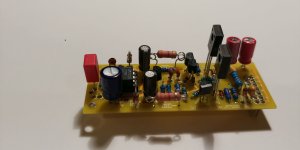
So, being nostalgic, I decided to built another one, this time not quasi, but proper complementary design,
with 3 pairs of output devices, and LMK type front end, including original Germanium transistor
in Vbe multiplier, just like described in the very 1st post in this thread.
Rails are 30V, so this should be good for 30W of honest power.
Idle current is set to 50mA per device. With these little heatsinks it runs pleasantly warm,
but not hot.
If natural gas prices for haeating will keep going up, as they are,
I guess I'll be using Beta Nirvana amp much more, to keep my office nice and warm in these winter nights.
Output DC offset is 0.1 mV.
The build was very easy to put together, the real amp matches the sim perfectly,
everything worked right away, without any tinkering. Just adjust idle current, and that's it.
Amp sounds great, again - indistinguishable from any other amp I built in this thread.


where I shared my experience with fake (or defective ?) TIP2955 transistors.
Why anybody would be using TIP3055/2955 in 21st century, for an audio amp?
While ago I noticed I'm listening more and more to TIP3055 Quasi amp built
earlier in this thread, and it seems to me that this little amp performs great.
I really do not see anything wrong with it, the audio it produces is indistinguishable
from any other amp I built. Great bass, sopranos, etc....
And cheap and easy to build.
So, being nostalgic, I decided to built another one, this time not quasi, but proper complementary design,
with 3 pairs of output devices, and LMK type front end, including original Germanium transistor
in Vbe multiplier, just like described in the very 1st post in this thread.
Rails are 30V, so this should be good for 30W of honest power.
Idle current is set to 50mA per device. With these little heatsinks it runs pleasantly warm,
but not hot.
If natural gas prices for haeating will keep going up, as they are,
I guess I'll be using Beta Nirvana amp much more, to keep my office nice and warm in these winter nights.
Output DC offset is 0.1 mV.
The build was very easy to put together, the real amp matches the sim perfectly,
everything worked right away, without any tinkering. Just adjust idle current, and that's it.
Amp sounds great, again - indistinguishable from any other amp I built in this thread.
Attachments
Last edited:
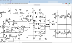
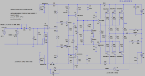
This amp has nothing to do with the LMK style amps that initiated this thread,
but I guess it does qualify as 'unusual' - I know of only 2 amps with similar topology.
Hafler P7000 was designed by Jim Strickland (after David Hafler sold his company),
and I tried to re-create this amp in slightly simplified version.
It has interesting push-pull VAS - that the reason I wanted to give it a try.
I have positive recollections of the sound quality of these amps (also Hafler 9505,
from around 20 years ago). They were dead silent - no noise, no hum, and sounded terrific.
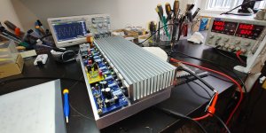
Now, this new amp here - the real-life build worked right away and matched LT Spice simulation
very well. There was no need to adjust anything.
It runs with idle current of approx 50mA per output Fet.
DC output offset - 1mV. Runs very stable.
Didn't try music yet.
Will build 2nd channel, and then do final musical tests.

but I guess it does qualify as 'unusual' - I know of only 2 amps with similar topology.
Hafler P7000 was designed by Jim Strickland (after David Hafler sold his company),
and I tried to re-create this amp in slightly simplified version.
It has interesting push-pull VAS - that the reason I wanted to give it a try.
I have positive recollections of the sound quality of these amps (also Hafler 9505,
from around 20 years ago). They were dead silent - no noise, no hum, and sounded terrific.
Now, this new amp here - the real-life build worked right away and matched LT Spice simulation
very well. There was no need to adjust anything.
It runs with idle current of approx 50mA per output Fet.
DC output offset - 1mV. Runs very stable.
Didn't try music yet.
Will build 2nd channel, and then do final musical tests.
Attachments


Nice work Minek, always fun to read about and follow your projects.
Cheers!

Cheers!
The only funny thing with testing this amp, was that instead of BC556 (pnp), I soldered BC546 (npn).
The print on the transistor was very weak/unreadable, or perhaps I need new glasses, and it took me a while to figure
this out, and replace the transistor. After that, everything worked perfectly.
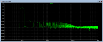
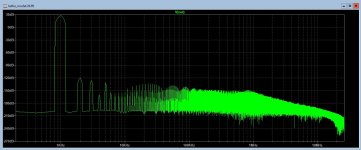
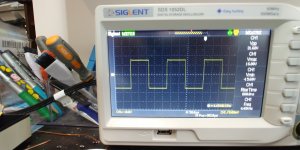
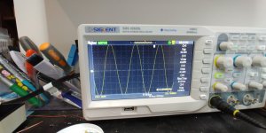
Judging from the rise time in square waves, slew rate of this amp should be higher than simulated.
Thd is already very low; it it seems like a very good amp so far.
I'm working on the 2nd channel now.
The print on the transistor was very weak/unreadable, or perhaps I need new glasses, and it took me a while to figure
this out, and replace the transistor. After that, everything worked perfectly.
Judging from the rise time in square waves, slew rate of this amp should be higher than simulated.
Thd is already very low; it it seems like a very good amp so far.
I'm working on the 2nd channel now.
H
HAYK
I am trying to run the .asc file. Downloading the minek.lib gives error multiple As. I copied the mosfets models and I get error, unknown subcircuit called In xm 1 n003 n006 n016 fqa27n25. Any idea what to do?
Last edited by a moderator:
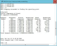
You don't need to download or change anything. Just run asc file as is.
If you see "multiple definitions" warnings, you can ignore them....
These are mostly new definitions overriding internal LT Spice models.
E.g. for BC546B.
My log attached.
If you see "multiple definitions" warnings, you can ignore them....
These are mostly new definitions overriding internal LT Spice models.
E.g. for BC546B.
My log attached.
Attachments
Last edited:
Hello Minek,
a really interesting amplifier.
I took a closer look at the simulation and played around with it a bit, as I've been tinkering with a similar amplifier concept for two years and collecting my experiences. Since my experience is that component noise is an enemy of such designs and your simulation models calculate very low noise, I would be very interested to know what you measure as signal noise distance.
Regards Tim
Looks like I'll have to add small heatsinks for Q3/Q4. They are little bit too hot to let them run naked.
Last edited:
Of course, I had to mess with this. I expected that removing the "unnecessary" bits would compromise performance, but it seems to be unchanged after trimming. This is much the same as your other amps and gives 5ppm THD at 16mA bias but doesn't get better with more. The output bias is sensitive to VAS current which is sensitive to the stage before... Maybe a tweak to the VBE multiplier could improve that?
Attachments
Steve, I have to confess that I tried to build an amp almost exactly like the one you proposed,
and also a few similar ones; variations of the same topology.
They sim very well, but I was unable to make them stable in real world.
So far from my experience, it's been very difficult to stabilize any real-world build of an amp with slew rate over 100-120 V/us.
For these amps, real life behavior differs a lot from simulations..
I'm only posting here successful amps, but for every successful one, there is a few bad ones 🙂
Last edited:
- Home
- Amplifiers
- Solid State
- Unusual amp from 1987