If is happening in primary than is the effect of all transformer parameters , current drawn , not just the core , you can't know .
Using the generator solid state output is meaningless for tube amplifiers
If the core would be so important there would be tests just swapping cores on the same transformer , so far I saw none . Even so ,the inductance changes , the current drawn is different so it is not simple to prove something
Using the generator solid state output is meaningless for tube amplifiers
If the core would be so important there would be tests just swapping cores on the same transformer , so far I saw none . Even so ,the inductance changes , the current drawn is different so it is not simple to prove something
Last edited:
And it is also in the primary, of course. That’s why it makes a difference using a lower output impedance (Ri<<Ra)
If we attack of secondary of an OT with a transistor amplifier that has very low output rezistence, very high frecuency band and low THD pus primary/secondary adaptation resistor, the harmonic distortions measured successively in the primary and secondary will be identical. In the case of an SE, the Miller effect intervenes, the saturation of the core so inherently the frequency band will be lower but the THD will be preserved in the primary and secondary

Can you give a schematic of what you mean with primary/secondary adaptation resistor? are they serie/parallel ?
But you are serious or not?Can you give a schematic of what you mean with primary/secondary adaptation resistor? are they serie/parallel ?
I sent more than one time the basic circuit for reverse mode.
Have you understood or not?
In this configuration you can also use as load on primary a that is similar to a Rp of tube or you can use the Z given from the R on secondary x the ratio>2 , just to see what happen; also this was shown on my old thread.
And it is possible what happen changing the Z load on primary; this is a fine way to confirm the theory around the Zs of the generator.
Then I have tested a bobbin with two different C nucleus, one the standard and one the AMCC 100 Metglas.
It don't fit perfectly but the differences were noted; I try to find where I put the diagram ( almost 5 years ago).
I take my phrase on post 54:
And the Thd is related to a type of iron AND signal level
change in this way, better I think:
And the Thd is related to a type of iron AND signal level given a fixed Zs.
Walter,But you are serious or not?
I sent more than one time the basic circuit for reverse mode.
Have you understood or not?
In this configuration you can also use as load on primary a that is similar to a Rp of tube or you can use the Z given from the R on secondary x the ratio>2 , just to see what happen; also this was shown on my old thread.
And it is possible what happen changing the Z load on primary; this is a fine way to confirm the theory around the Zs of the generator.
Then I have tested a bobbin with two different C nucleus, one the standard and one the AMCC 100 Metglas.
It don't fit perfectly but the differences were noted; I try to find where I put the diagram ( almost 5 years ago).
I take my phrase on post 54:
And the Thd is related to a type of iron AND signal level
change in this way, better I think:
And the Thd is related to a type of iron AND signal level given a fixed Zs.
if you read the thread then you could understand that i was not asking you.
Can you give a schematic of what you mean with primary/secondary adaptation resistor? are they serie/parallel ?
Attachments
Hi
If you take a signal with a partitor at the secondary of first OT trafo and check the freq. answer, thd vs freq and, in case FFT you can compare with the one comes from the amp.
This because it is difficult to have a test set that can accept 70 Vrms ( AP can handle)
It is interesting as one shot comparision
In this way you have a simultaneos verification also with the varable signal input on ss amp to check different level
To make it more clear: if you place a restistor in serie with the amplifier at that moment you change it in to a new situatie with an sourse with "high" output impedance.Can you give a schematic of what you mean with primary/secondary adaptation resistor? are they serie/parallel ?
Guys, what are you talking about? Every test set up you are suggesting is good only to compare one trafo to another, that is all.
The true test could be done only in the real environment, with the output tube the trafo is intended to work with, real voltages, currents and signals. And of course within the expected frequency range, and the expected load (AC). Besides testing for performance, you gotto listen to real music in the real setup.
Now, if your trafo produces THDs (within the working range), it is a piece of crap, and should be in the trash, not in your Amp.
Dima, you opened up a discussion that brought out nothing, but a bunch of crows, burking at each other (sorry guys, but it sounded like that), Dima, you should have had to know better 🙂.
With respect to everyone,
Andre, NJ
Some reading for all of us:Guys, what are you talking about? Every test set up you are suggesting is good only to compare one trafo to another, that is all.
The true test could be done only in the real environment, with the output tube the trafo is intended to work with, real voltages, currents and signals. And of course within the expected frequency range, and the expected load (AC). Besides testing for performance, you gotto listen to real music in the real setup.
Now, if your trafo produces THDs (within the working range), it is a piece of crap, and should be in the trash, not in your Amp.
Dima, you opened up a discussion that brought out nothing, but a bunch of crows, burking at each other (sorry guys, but it sounded like that), Dima, you should have had to know better 🙂.
With respect to everyone,
Andre, NJ
https://www.audiofaidate.org/it/materiale/20_010_040_001_Hodgson.pdf
That is what the article says:
By the way I read that article many years ago.
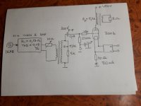
Exactly, the OT used for attack of the tube is identical to the one in the anode and the adjustable resistor of 10 ohm makes the correct Zp/Zs adaption ( sqw 10 Khz so that there are no overcresters on the ascending/descending fronts). The simultaneous two channel verification of the oscilloscope of the inputs signal on Ug and the OT secondary will show the influence of the bias current, the Rp of the tube and with a dB-meter frequency bandHi
If you take a signal with a partitor at the secondary of first OT trafo and check the freq. answer, thd vs freq and, in case FFT you can compare with the one comes from the amp.
This because it is difficult to have a test set that can accept 70 Vrms ( AP can handle)
It is interesting as one shot comparision
In this way you have a simultaneos verification also with the varable signal input on ss amp to check different level
Your schematic in post 67 has variable voltage distortion because of the 10 Ω rheostat.Exactly, the OT used for attack of the tube is identical to the one in the anode and the adjustable resistor of 10 ohm makes the correct Zp/Zs adaption ( sqw 10 Khz so that there are no overcresters on the ascending/descending fronts). The simultaneous two channel verification of the oscilloscope of the inputs signal on Ug and the OT secondary will show the influence of the bias current, the Rp of the tube and with a dB-meter frequency band
You did not understand, the adjustable resistor only sets the correct adaptation of the transformer used for the attack, after which only level in the generator/amplifier with transistors with an insignificant THD is changedYour schematic in post 67 has variable voltage distortion because of the 10 Ω rheostat.
Attachments
You did not understand, the adjustable resistor only sets the correct adaptation of the transformer used for the attack, after which only level in the generator/amplifier with transistors with an insignificant THD is changed
Right!
It was difficult to explain to some people this concept.
Every OT is a bi-directional device when properly colsed at the terminals with a linear device as resistors.
I suppose that your test set up is similar to mine.
And this helps not only for s.e. but also for pp with proper setting ( and the possibiity to switch or not the dc current)
One note.
I am reding the document by Hodson; he copied and past some concept fro the Partridge articles ( 4 articles) that I have already mentioned. Then there are some concepts that are hazardous.
another note:
SHOULD BE not IS a linear device.
Every OT is NOT a linear device; if you look on the equivalent circuit you can understand why, maybe.
If an OT could be linear, all the limit on Freq. respnse, THD, phase are solved !! ( there is a parasitic form power tube but we can consider them a little things 🙂)
Maybe you both read, or tried to read those articles but you both ignore what is written by Partridge. It’s no problem that you don’t understand the theory, you are free to do measurements your way but for me and others it is clear that you do useless measurements.
As you want.Maybe you both read, or tried to read those articles but you both ignore what is written by Partridge. It’s no problem that you don’t understand the theory, you are free to do measurements your way but for me and others it is clear that you do useless measurements.
Bye
I'm just saying, Walty, just that $50000 in measuring equipment doesn't save you from making mistakes.
- Home
- Amplifiers
- Tubes / Valves
- Q: Measuring Frequency Response of PP Output Transformer