Hopefully some experienced people can offer advice here.
I'm sitting on a large stash of 40 x Peerless TC9FD18-08 and 40 x SB acoustics SB26STCN with the intent of building a large 2 way array inspired by the fullrange version many people have already built. The reasoning for the 2 way implementation of these drivers is trying to get a more dynamic and coherent HF response - I like the way the TC9 drivers sound up to about 8k, but the HF response past that isnt that great. The additional reasoning was having a tighter driver spacing thanks to the smaller diameter soft dome drivers to reduce combing. These little soft domes sound very good being they only cost me $26 each. I've used these in other projects and they sound alot like a higher end SB soft dome, so IMO they are a worthy choice for an array.
I planned on a 20 element array per side for both LF and HF sections using the tightest possible driver spacing. This means I may truncate the HF driver faceplates to get them spaced even tighter for the least amount of combing. The processing, EQ and crossover was initially going to be DSP, then active analog once the main EQ curve and crossover was established.
I took some inspiration from these threads -
www.diyaudio.com/community/threads/full-range-tc9-line-array-cnc-cabinet.303417
www.diymobileaudio.com/threads/lord-of-the-waves-the-two-towers-a-25-driver-line-array.114489
www.roger-russell.com/ids/ids.htm
Does a 2 way implementation of this type of an array sound like it has the advantages I'm looking for, or am I opening up a bigger can of worms? I know the horizontal dispersion will suffer a bit with the side by side driver arrangement, but i wanted the more precise sounding treble of the SB soft domes with lower distortion and headroom to spare. Any constructive thoughts?
Attachments
Hi, I love the idea of tall line arrays using multiple lines. About the only new speaker project i even think about anymore (being so happy with synergies).Hopefully some experienced people can offer advice here.
I'm sitting on a large stash of 40 x Peerless TC9FD18-08 and 40 x SB acoustics SB26STCN with the intent of building a large 2 way array inspired by the fullrange version many people have already built. The reasoning for the 2 way implementation of these drivers is trying to get a more dynamic and coherent HF response - I like the way the TC9 drivers sound up to about 8k, but the HF response past that isnt that great. The additional reasoning was having a tighter driver spacing thanks to the smaller diameter soft dome drivers to reduce combing. These little soft domes sound very good being they only cost me $26 each. I've used these in other projects and they sound alot like a higher end SB soft dome, so IMO they are a worthy choice for an array.
I planned on a 20 element array per side for both LF and HF sections using the tightest possible driver spacing. This means I may truncate the HF driver faceplates to get them spaced even tighter for the least amount of combing. The processing, EQ and crossover was initially going to be DSP, then active analog once the main EQ curve and crossover was established.
I took some inspiration from these threads -
www.diyaudio.com/community/threads/full-range-tc9-line-array-cnc-cabinet.303417
www.diymobileaudio.com/threads/lord-of-the-waves-the-two-towers-a-25-driver-line-array.114489
www.roger-russell.com/ids/ids.htm
Does a 2 way implementation of this type of an array sound like it has the advantages I'm looking for, or am I opening up a bigger can of worms? I know the horizontal dispersion will suffer a bit with the side by side driver arrangement, but i wanted the more precise sounding treble of the SB soft domes with lower distortion and headroom to spare. Any constructive thoughts?
Ideally, I'd like a floor to ceiling line of some ribbon driver, and same length line of either 8"s or 10"s, with an in between same length line of around 2 1/2 -3 1/2"s.
The ribbon line is to get true 1/4 WL spacing all the way up.
The 8"-10" line for the amount of low end displacement I'd like for use without a sub.
The intermediate line would be a size balancing act, depending on how low the ribbons go, and how high the 8-10" line goes while keeping 1/4WL spacing. A lot of folks say 1/2WL spacing holds the line....I'll study that hard if i ever take off on this...
Ok, I say all that just to reveal my biases implicit in my comments about your proposal....
I like the idea of a probably better sounding HF/VHF using the SB26STCN, than maybe what the TC9 provides.
Problem i see is the amount of chassis the SB26STCN has vs it's radiator size.
Looks like even if you whittle it down to the max, it will still be close to 2" c2c between them. So it might be a bit better sounding, but I think comb filtering isn't improved as much as I'd hope, going from a 2.7" diameter cone in the TC9 to a 1" dome in the SB.
Another thing I'm wondering, ....don't you need more of the SB than the TC9s to keep equal length lines?
Even if you left the SB's size alone, don't you need 84/72mm (their tight pack dimensions) or 1.17X the number of TC9's ? So 23 SB's in this case.
Or 1.5X the number of TC9's if the SB's are whittled down to 2".
I guess on the whole, I think the two drivers you have are too close to each other to be used in a two-line array.
I'd either use a single small driver that spaced tighter, like maybe what Jim Griffin used; or go for as small a HF/VHF I could extend into a line, paired with a second line something distinctly larger.
my 2c

Mark, thx for the reply and suggestions. I agree with you considering HF chassis spacing. The difference is about 13mm between both LF and HF driver size - 72mm for the SB26 and 85mm for the TC9. I was going to make the HF line shorter by 26cm (20 x 13mm) and center the lines, but I'm not sure what that will do to the horizontal main lobe off axis response. I dont even know if that's critical or not. Almost everything I build is large 3 way or 4 way stuff - I don't mess with little stuff anymore as it doesnt play loud enough. I guess i should order 8 more SB26 to make up for the difference depending on how that all works out total impedance wise. Other reasons I chose this tweeter for a line was the lack of ferrofluid, copper in the VC gap, low resonance for its size and the larger xmax, all in hopes for a low crossover point. I cant even imagine how much dynamic reserve I'll have with that many tweeters arrayed.
The TC9 was an obvious choice thanks to its transparency in the midrange along with the decent efficiency for such a small driver.
My ceiling is 12 ft and the tweeter line would be 56 inches for 20 HF elements. That means i should probably double the line length, but the cost is already up there at about 1700 bucks just for drivers. My listening distance will be around 10 ft, so I dont know how that factros into how far the LF line carries compared to HF.
I was toying with the idea of doing a 3 way design using 12 x Scanspeak 18W-5537G-01 per side in SLOB arrangement, so the TC9s wouldn't have to carry that far as a line down low, say past 300 Hz. I wouldn't run the TC9s open baffle though. Yes, thats alot of drivers... lol. Maybe its worth the effort. I just need a way to sim all this. Luckily I have a very understanding Mrs that deals with my insanity.
Attachments
The design will excel if you do a few things......
First truncate three sides of each tweeter to get the center distance down to 2.25” and reducing the c to c distance of the woofer to tweeter
Cross the tweeters at 1.6khz to your woofers.....1st order.......26 of them can handle this without breaking a sweat. Now you’re well within the 1/4 wavelength of the center to center spacing. Sounds like a really fun speaker....good thing you accumulated the drivers before this crazy inflation!
Mark's reply above highlights two important issues, the line lengths need to be the same to have the same vertical directivity, (any significant mismatch there could be problematic) and the horizontal CTC places greater demands on the HF driver when trying to avoid lobing.Any constructive thoughts?
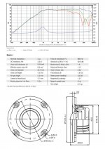
Based on the magnet size of the tweeter and the frame size of the TC9 the minimum CTC I calculated would be 65mm with some surgery to the tweeter, that would be ~1300Hz XO frequency for 1/4 wl spacing.
I think you would get quite a lot of insight into the response with different options by simulating them in Vituix, @nc535 posted an array template in his array thread that would give you a head start.
You might find that you need quite a few more tweeters to get the best response, truncated arrays of any kind seem to have the most compromises.
Quite a bit can be done with the right kind of EQ or frequency shading filters to reduce combing and improve the upper end response, improving on that with a tweeter and not compromising on other more significant response features is not a simple task. But getting the EQ right in the first place is no simple task and I doubt there are that many people who have managed it for themselves, as the recipe for everyone is slightly different.
I'm clearly going into this whole project with many challenges ahead, which is why I'm asking those who have done domestic hifi line arrays a few times having learned from their mistakes. This is completely new territory for me and despite the knowledge of speaker building, there's way more to this type of speaker design (to get it right) than anything I've ever built, as I come from the large 3 ÷ 4 way studio monitor style build world.
The 1/4 wavelength rule appears to be the dominating thing in getting this somewhat right. I'm usually more comfortable running a tweeter resonance LCR notch when running a shallow filter close to Fs, even though the lower mid demand is small having this many drivers along with coupled gain. I could have bought cheaper tweeters without faceplates, but I didn't want to justify quantity with lower price and end up with mediocre HF compared to most typical budget soft domes. The thing making this worthwhile for me is the fact I'm starting with a tweeter that actually sounds good regardless of price. I would rank the SB26STCN as good as most upper double digit priced Morel or Scanspeak. I don't have an issue chopping the faceplate a little to get spacing tighter and I realize needing to buy a few more units to do it right.
The TC9 drivers are tough to flush mount from the front. I may fabricate a thin front cover panel and bevel the driver openings. That will at least hide the basket and time align the drivers better, which is critical for me. Question is how big of an air space I need for the TC9s if they're not doing anything below 200 or so Hz? I would do an open baffle if I had more room behind the speakers to get them away from the rear walls. That one is still up in the air, depending on how it affects dimensions, weight and build complexity.
The EQ issue isn't that big for me. I can duplicate the DSP settings with an analog circuit as long as there aren't any time delays, which I don't foresee. Too bad a passive network is too much of a loss in headroom, otherwise it would be more practical to do. I may still be able to do a passive line level filter depending on how much attenuation of overall drive level there is to flatten it out. There should be decent LF headroom with 12 x 7" drivers per side in SLOB configuration. The EQ required for that may end up coming from the front end of some plate amps I have (Speakerpower SP1-700) or a Parasound HCA2200. I definitely need to use a passive LCR for the tweeter to dampen the resonance mechanically at the tweeter VCs. The rest will be line level. I can't imagine how much HF dynamic reserve there will be while running a 1st order filter. There won't be any skimping on the DC blocking cap for the HF. I want to avoid an op amp based crossover here unless its absolutely needed.
Either way, I still have alot of homework to do. If anyone has a suggestion regarding the line length, please let me know. I can't practically run the full length from floor to ceiling which is almost 13ft. That would be double the amount of drivers... yikes! Then there's the baffle width and profile issue. Wider is probably better if its mated with a SLOB LF array and would help array coupling gain. I could end up with high 90s dB/W in the LF alone and close to that in HF.
I'll make it even easier: https://www.diyaudio.com/community/...-corner-placement.337956/page-28#post-6205129
That's the model from @nc535 to give you a head start. Next step is making a driver model for the tweeter and adding it in Vituix.
Try and simulate the array with tweeter line to see what you get. Way better than to go in blind. Don't forget that the baffle shape will influence the outcome as well.
In this case I think a pretty wide baffle with large round-overs would be easier to work with, due to the two lines of drivers. Think of the shape of the big "Genesis" and their forefather, the IDS arrays. (but do mount your driver lines closer together than seen here. the ribbons are mid-ranges! Go figure...)

(disregard the woofer towers here, the shape of the main arrays will help hide finding the position of the drivers trough diffraction. oval shape
with rounded corners. Maybe even rounder than these are)
Do buy the extra tweeters, it doesn't make sense to quit thinking about the possible outcome to save a few bucks. The details do matter, all of them.
Actually, don't buy anything yet, not until you get the sim right. It won't be easy, but it may well be worth your while.
The difficulty isn't in the technical part of the EQ. That is always going to be easy. The difficulty is how to get, or even know, what you want!
That alone makes a remarkable difference. Run the sims and it may become more clear as to why this can be tricky.
If you want an even better prediction of what to expect in the room, model the first floor and ceiling reflections too. Even though Vituiix gives
you the results with the option box for reflections, modeling it will provide you with the in-room IR, upon which you can base the EQ decisions.

an example of a full range array with modeled floor and ceiling reflections. The IR predictions this gets you help to give insight to possible EQ schemes.
Another thing to think about is the placement in the room... parallel planes (and ridges) to the arrays will have pretty equal reflection times. You don't want
that. If you're not going to run them down low, you can get them away from these planes and ridges (like side walls). Everything else will be averaged away
by the many drivers in the array. If you want to keep options open, give the drivers just over 2 liter per driver. It would be foolish to set the bar
ahead of time as to where you want to cross them. How are you going to do the frequencies from 160 HZ and down? It will be hard to find
something that can compete with the arrays, unless you make it: an array. The answer here is in multiples. It's why they act different and what
makes them do what they do. So even at bass frequencies you want multiples to keep up and be able to adjust to the room. That could mean you'd need the
array run a little lower in frequency than expected, depending on the room and placement options.
I wouldn't touch an OB array... these things are hard enough to figure out on their own, last thing you'd need is another unpredictable variable (the room).
About line length? Even that will be more clear from modeling, the closer to full length floor to ceiling, the better. For practical purposes if you're above roughly
70% of floor to ceiling length, you'd be close enough. Sim it though! That's the cheapest part of the whole project! 😀
While SLOB bass array might be a worthwhile addition to these arrays, don't get those "sliths" on the front side of the arrays. Think about what I said about parallel planes and ridges. They potentially give away the position of the (mid) drivers, you don't want that. That's why you'd want either a wide baffle or a very small one...
And round shapes without sharp corners. With a line of drivers this becomes even more important. Or bend it like a CBT to avoid that problem, but start a series of
other considerations in the process. It would be easier to time align the separate bass towers than to hide the effect of these ridges disturbing the outcome.
If you're using the woofers where they are omni anyway, you could place them at the back, and time align.
That's the model from @nc535 to give you a head start. Next step is making a driver model for the tweeter and adding it in Vituix.
Try and simulate the array with tweeter line to see what you get. Way better than to go in blind. Don't forget that the baffle shape will influence the outcome as well.
In this case I think a pretty wide baffle with large round-overs would be easier to work with, due to the two lines of drivers. Think of the shape of the big "Genesis" and their forefather, the IDS arrays. (but do mount your driver lines closer together than seen here. the ribbons are mid-ranges! Go figure...)
(disregard the woofer towers here, the shape of the main arrays will help hide finding the position of the drivers trough diffraction. oval shape
with rounded corners. Maybe even rounder than these are)
Do buy the extra tweeters, it doesn't make sense to quit thinking about the possible outcome to save a few bucks. The details do matter, all of them.
Actually, don't buy anything yet, not until you get the sim right. It won't be easy, but it may well be worth your while.
The difficulty isn't in the technical part of the EQ. That is always going to be easy. The difficulty is how to get, or even know, what you want!
That alone makes a remarkable difference. Run the sims and it may become more clear as to why this can be tricky.
If you want an even better prediction of what to expect in the room, model the first floor and ceiling reflections too. Even though Vituiix gives
you the results with the option box for reflections, modeling it will provide you with the in-room IR, upon which you can base the EQ decisions.
an example of a full range array with modeled floor and ceiling reflections. The IR predictions this gets you help to give insight to possible EQ schemes.
Another thing to think about is the placement in the room... parallel planes (and ridges) to the arrays will have pretty equal reflection times. You don't want
that. If you're not going to run them down low, you can get them away from these planes and ridges (like side walls). Everything else will be averaged away
by the many drivers in the array. If you want to keep options open, give the drivers just over 2 liter per driver. It would be foolish to set the bar
ahead of time as to where you want to cross them. How are you going to do the frequencies from 160 HZ and down? It will be hard to find
something that can compete with the arrays, unless you make it: an array. The answer here is in multiples. It's why they act different and what
makes them do what they do. So even at bass frequencies you want multiples to keep up and be able to adjust to the room. That could mean you'd need the
array run a little lower in frequency than expected, depending on the room and placement options.
I wouldn't touch an OB array... these things are hard enough to figure out on their own, last thing you'd need is another unpredictable variable (the room).
About line length? Even that will be more clear from modeling, the closer to full length floor to ceiling, the better. For practical purposes if you're above roughly
70% of floor to ceiling length, you'd be close enough. Sim it though! That's the cheapest part of the whole project! 😀
While SLOB bass array might be a worthwhile addition to these arrays, don't get those "sliths" on the front side of the arrays. Think about what I said about parallel planes and ridges. They potentially give away the position of the (mid) drivers, you don't want that. That's why you'd want either a wide baffle or a very small one...
And round shapes without sharp corners. With a line of drivers this becomes even more important. Or bend it like a CBT to avoid that problem, but start a series of
other considerations in the process. It would be easier to time align the separate bass towers than to hide the effect of these ridges disturbing the outcome.
If you're using the woofers where they are omni anyway, you could place them at the back, and time align.
Last edited:
Thanks man! I was hoping you would show up here.. great info and massive help! This is what I needed to move forward.
Yes, I'm going to fire up Vituix and see what happens. I agree with you on the OB thing. I was only going to run the LF (12 x 7") in OB slot loaded array since i really like the way it sounds that way. Regarding the line length, I need to assess the cost of making it 8 ft, which means 10 more TC9 and 15 more SB26 per side, about $800 worth of extra drivers... ouch!
Yes, I'm going to fire up Vituix and see what happens. I agree with you on the OB thing. I was only going to run the LF (12 x 7") in OB slot loaded array since i really like the way it sounds that way. Regarding the line length, I need to assess the cost of making it 8 ft, which means 10 more TC9 and 15 more SB26 per side, about $800 worth of extra drivers... ouch!
Yeah, I remember the chassis trimming you had to do with your setup. That is definitely ambitious and somewhat risky. I have alot of extra chassis for pro sound builds laying around to be utilized. The money is easy to spend on "hoarding" all those drivers but it all doesn't just build itself... lol
That's not the scary bit, cutting the frames on all of them is the scary bit! 😬I bought 50+ Scan Speak 10F's... I don't scare easily 😀
If doing a 2-way line array, I would use this tweeter. Its frameless and allow you to minimize the CTC
typmpany OC25 tweeter
"only" $20 in quantity
typmpany OC25 tweeter
"only" $20 in quantity
I appreciate the suggestion. Unfortunately Fs is too high on that one, plus it has ferrofluid, so if it dries up or seeps out, its a sealed unit so it ends up being junk. I also prefer the sound of no ferrofluid and the xmax on the SB26 is at least 1.2mm with decent efficiency and the VC former is vented with a lower total Q. There is about a 5mm spacing benefit from that Tymphany tweeter, but rear mounting isn't as easy as it looks to get it aesthetically precise to look at, unless you have access to a cnc. I can get 50mm CTC spacing with the SB26If doing a 2-way line array, I would use this tweeter. Its frameless and allow you to minimize the CTC
typmpany OC25 tweeter
"only" $20 in quantity
I would reserve you're judgement until you have found the EQ settings that give you the sound you are after. Certainly the great bulk of my EQ could be analogue active but not all of it. I have not found my own speakers to respond well to anechoic EQ, they only sound right when measured and tweaked based on in room measurements. I wished this were not so, as it creates an element of alchemy that I don't like. The best sounding EQ to me uses settings that break all the rules of how to EQ and no matter how hard I tried, nothing that followed any sensible practice was as good. So now I just accept it 🙂The EQ issue isn't that big for me. I can duplicate the DSP settings with an analog circuit
If you want to get a smooth diffraction response without peaking it is important to minimize the "flat" baffle area. That does not mean the baffle has to be small but the profile must start as soon as possible. You will find some simulations I made in the link below. The difference a 6mm front chamfer and smooth enclosure shape had was significant. An enclosure like the Genesis could work well as anything that is wide and shallow creates a natural cardioid directivity to the low midrange.Then there's the baffle width and profile issue. Wider is probably better if its mated with a SLOB LF array and would help array coupling gain. I could end up with high 90s dB/W in the LF alone and close to that in HF.
https://www.diyaudio.com/community/...ver-full-range-line-array.242171/post-6524791
The areas of diffraction peaking in my own speakers have always represented a difficult area to EQ, where a compromise had to be reached. They still sound great but I do wonder if they would sound better overall if that compromise was removed.

Taylor’s research shows that a shorter tweeter array is a good thing.
https://p10hifi.net/TLS/downloads/taylor-line-array.pdf
dave
https://p10hifi.net/TLS/downloads/taylor-line-array.pdf
dave
Because in the application of a PA in a church he didn't want to reduce the main vertical beam by extending the line.Taylor’s research shows that a shorter tweeter array is a good thing.
In a home setting extending the line generally has positive effects and reducing the vertical beamwidth isn't a problem.
Both you guys make very valid arguments regarding the HF line length. With a shortened HF line, my main question would be this - If for the moment i look at the design as strictly LF and HF array on a profiled baffle (for simplicity sake without the 12 driver sub LF array), with a shorter HF array, is it more important to center the HF array in regards to listening height or is absolute vertical symmetry (centered in relation to the LF line) the absolute rule to follow?
I also would assume that a shorter HF line will cause an abrupt bump/shift in phase response off axis and therefore bad power response?
From an EQ perspective, I completely understand the pitfalls and unpredictable results with integrating the finished product to the room acoustics. It can be exhausting to find a good setting that caters well to most styles of music and recordings. To make matters worse,, these speakers are going into my living room which has a very awkward, unsymmetrical floor plan. The main listening area is 15ft wide carpeted concrete flooring and 13ft ceiling height, but to the right side of that carpeted section (just past right speaker location), it opens up to a 7ft wide section of tiled hallway with vaulted ceiling (18ft peak). Total width (carpeted + tiled hallway) is 22 ft and depth is 29ft. The vaulted ceiling section (hallway past right speaker location) runs almost the whole 29ft depth of the living room and continues to the right past the front wall of living room (speaker location) into an open great room area that shares the vaulted ceiling. Simply put, the whole listening area is a 13' height, 29' depth, 15' width room with the right side completely open. I trried to center the speakers to the total width of living area with consideration to the closest right side wall, but there is a bias towards the left side wall for the sake of visual esthetics. Quite remarkably the whole setup doesn't really affect stereo imaging, but that's with my old B&W 802s. Other speakers with different dispersion characteristics will suffer in this location, as was the case with some larger 3 way PMC monitors I used to have.
- Home
- Loudspeakers
- Multi-Way
- 2 way TC9 array with SB26STCN