Thanks for that illustration. I could take more than an additional 5mm off that spacing by rotating the tweeter 45 deg and chopping off 2 of the mounting holes. That however compromises mounting flange integrity to some degree. Not sure if its worth the risk. Could have significant benefits.
Boy its hard to shut my brain off from all this. I picked up the lumber for my big 3 ways today which are a whole different animal than this line array project. Well, maybe not so much. The bottoms will run B&C 18PZB100s and may also double as subs for the lines... we'll see. These 18s are really snappy and tight into the lower mids while reaching low into the upper 30s. I have to get some sleep so I dont end up with a migraine. I have 2 long bass gigs lined up for tomorrow... 😱
Keep in mind that you'd want the tweeter line as close as possible to the line of mids. That means more shaving...Thanks for that illustration. I could take more than an additional 5mm off that spacing by rotating the tweeter 45 deg and chopping off 2 of the mounting holes. That however compromises mounting flange integrity to some degree. Not sure if its worth the risk. Could have significant benefits.
You'll get some answers to these questions while simulating this. Not that you'd get an indication of the sound that belongs to the specific choices but at least it would be an educated guess.Both you guys make very valid arguments regarding the HF line length. With a shortened HF line, my main question would be this - If for the moment i look at the design as strictly LF and HF array on a profiled baffle (for simplicity sake without the 12 driver sub LF array), with a shorter HF array, is it more important to center the HF array in regards to listening height or is absolute vertical symmetry (centered in relation to the LF line) the absolute rule to follow?
I also would assume that a shorter HF line will cause an abrupt bump/shift in phase response off axis and therefore bad power response?
The only thing I didn't like about the SB26 tweeter was its large face plate. I would be more concerned about the vertical spacing, which determines the onset of combing, than the HF to LF line spacing.
Simulation results with frequency tapered arrays confirm that shorter HF arrays are good. the shorter the array, the lower the phase shift from the drivers near the ends which causes the combing. But a shorter array may have a greater response variation with height and even a short array will have a narrow vertical beam so the length of the tweeter array must cover and exceed the range of listening heights. The response variation with listening height is why I think the array needs to be simulated to find a tweeter array length that works.
If you only care about seated listening the narrow vertical beam and response variation with height isn't a problem. If you want great seated response that remains good for a standing listener, you are likely to need to shade and/or frequency taper the array. I did a lot of simulations of frequency tapering and shading but was so happy with my DSP equalized floor to ceiling array response in my primary LP, that I never implemented any of them. Those arrays were confined to my garage, which was my exclusive domain.
There are several things that need to be EQed:
1. the single driver response
2. the -3db per octave line array roll off with frequency
3. the (optional) shading and/or frequency tapering to smooth the vertical response or combat combing
4. room response irregularities in the LF and lower mid range
Conceptually, its easier to think of them separately but in the end you want a single filter. I wouldn't try to do it passively without first having verified the response with the DSP equivalent. You can get in the ball park for # 1 &2 with analog/IIR filters. If that wasn't good enough, I would take the driver measurements into Vituix and find shading coefficients and frequency tapering that made it (the vertical response) better. That too can be done passively as Wesayso has shown. If it were me, I would still want a layer of DSP room equalization on top of all that.
Any EQ you do is going to be position dependent in y and z and likely the room will affect x. Even with drivers whose individual response is perfectly flat and smooth, the formation of a line makes equalization and thus position dependence unavoidable. That is the one drawback of the line array in the home and perhaps the price you pay for eliminating floor and ceiling reflection nulls. Within that limitation which can easily spans multiple seats on a couch, the LA can be great.
the tweeters would have a smaller pitch, so won't you need more of them to match the height of the 20 TC9F's?Hopefully some experienced people can offer advice here.
I'm sitting on a large stash of 40 x Peerless TC9FD18-08 and 40 x SB acoustics SB26STCN with the intent of building a large 2 way array inspired by the fullrange version many people have already built. The reasoning for the 2 way implementation of these drivers is trying to get a more dynamic and coherent HF response - I like the way the TC9 drivers sound up to about 8k, but the HF response past that isnt that great. The additional reasoning was having a tighter driver spacing thanks to the smaller diameter soft dome drivers to reduce combing. These little soft domes sound very good being they only cost me $26 each. I've used these in other projects and they sound alot like a higher end SB soft dome, so IMO they are a worthy choice for an array.
I planned on a 20 element array per side for both LF and HF sections using the tightest possible driver spacing. This means I may truncate the HF driver faceplates to get them spaced even tighter for the least amount of combing. The processing, EQ and crossover was initially going to be DSP, then active analog once the main EQ curve and crossover was established.
I took some inspiration from these threads -
www.diyaudio.com/community/threads/full-range-tc9-line-array-cnc-cabinet.303417
www.diymobileaudio.com/threads/lord-of-the-waves-the-two-towers-a-25-driver-line-array.114489
www.roger-russell.com/ids/ids.htm
Does a 2 way implementation of this type of an array sound like it has the advantages I'm looking for, or am I opening up a bigger can of worms? I know the horizontal dispersion will suffer a bit with the side by side driver arrangement, but i wanted the more precise sounding treble of the SB soft domes with lower distortion and headroom to spare. Any constructive thoughts?
Thanmks again everyone for your answers and time. Yes, next step is simming for sure. Are there any other programs that can help with this other than vituix? I've seen spread sheets but some of them don't really help with specific things I'm after, plus they're not very user friendly. This is all why I ask questions ahead of time so people with experience can share their thoughts. These are the answers you won't get from sims or the like ie what drivers to use, what baffle shape is best, what supporting hardware, etc.
Well sure, but the effects of combing and the like become more of an issue which is exactly what I'm trying to reduce through less CTC spacing, making the line already shorter than optimal, plus you have to cross lower to compensate. I'm already close to the tweeter resonance, so thats an issue.the tweeters would have a smaller pitch, so won't you need more of them to match the height of the 20 TC9F's?
A very very quick and rough test of 25x tweeter + 25x TC9 doesn't make me all that confident of the tweeter size:
(take it for what it is, a job of a few minutes work to whip up the sim with a tweeter this size, not based on directivity
information of this particular tweeter but a simple model made with the diffraction tool)

That 55 mm C to C doesn't seem to be all that attractive. 25 mids and 25 tweeters, crossed at 1300 Hz, first order. No shading.
The lobes (horn shaped) do rise a bit in frequency, the top end is wider in the vertical directivity plot, but horizontal gets skewed (obviously)
due to the tweeter line being about 70 mm beside the mids. Tweeter can perform more uniform than this, I just used standard settings
with the diffraction tool without optimizing the baffle, but it does show a diffraction-less baffle design becomes important. More care is needed
for a good model, but certain trends will be visible, no doubt.
Driver spacing:

CTC: 55 mm between tweeters, 70 mm between tweeter/mid
Even though this isn't a definitive sim in any way, shape or form, it does tell me that it wouldn't be worth it to me unless you can go for a
near seamless tweeter spacing like you could get with a ribbon etc.
Lots can be done to improve this particular sim, but is it worth it with this big of a CTC spacing?
I hope @profiguy will work harder to create a better, more believable sim before thinking of pushing forward this project.
The number of tweeters does not determine the onset of combing, though less tweeters will have a more narrow vertical sweetspot and suffer a bit less.
Here's what it looks like with 15 tweeters:

Which is why I said to wait with decisions like that until after it is simmed (properly, not this quick whip-up)
Anyone with a bit of time on their hands, please, do a better job than me here 😉.
(take it for what it is, a job of a few minutes work to whip up the sim with a tweeter this size, not based on directivity
information of this particular tweeter but a simple model made with the diffraction tool)
That 55 mm C to C doesn't seem to be all that attractive. 25 mids and 25 tweeters, crossed at 1300 Hz, first order. No shading.
The lobes (horn shaped) do rise a bit in frequency, the top end is wider in the vertical directivity plot, but horizontal gets skewed (obviously)
due to the tweeter line being about 70 mm beside the mids. Tweeter can perform more uniform than this, I just used standard settings
with the diffraction tool without optimizing the baffle, but it does show a diffraction-less baffle design becomes important. More care is needed
for a good model, but certain trends will be visible, no doubt.
Driver spacing:
CTC: 55 mm between tweeters, 70 mm between tweeter/mid
Even though this isn't a definitive sim in any way, shape or form, it does tell me that it wouldn't be worth it to me unless you can go for a
near seamless tweeter spacing like you could get with a ribbon etc.
Lots can be done to improve this particular sim, but is it worth it with this big of a CTC spacing?
I hope @profiguy will work harder to create a better, more believable sim before thinking of pushing forward this project.
The number of tweeters does not determine the onset of combing, though less tweeters will have a more narrow vertical sweetspot and suffer a bit less.
Here's what it looks like with 15 tweeters:
Which is why I said to wait with decisions like that until after it is simmed (properly, not this quick whip-up)
Anyone with a bit of time on their hands, please, do a better job than me here 😉.
Last edited:

I've pointed at this project before, but a multi-way array done well with an eye for detail would be the fractal array of bbutterfield:
https://www.diyaudio.com/community/...raight-cbt-with-passive-xos-and-no-eq.330031/
It would solve several problems that we run into here...
https://www.diyaudio.com/community/...raight-cbt-with-passive-xos-and-no-eq.330031/
It would solve several problems that we run into here...
I imagine you have come across it in your earlier research but Jim Griffin's line array paper has a good look at these sorts of issues, there is an analysis of the various trade offs inherent in shortening the tweeter line for practical reasons. This is where Vituix is very good at examining those options and what effect frequency or power tapering has on the response.Both you guys make very valid arguments regarding the HF line length. With a shortened HF line, my main question would be this - If for the moment i look at the design as strictly LF and HF array on a profiled baffle (for simplicity sake without the 12 driver sub LF array), with a shorter HF array, is it more important to center the HF array in regards to listening height or is absolute vertical symmetry (centered in relation to the LF line) the absolute rule to follow?
I also would assume that a shorter HF line will cause an abrupt bump/shift in phase response off axis and therefore bad power response?
"Tweeter Line Height. As for the woofer line length, the ideal tweeter line length would also extend from near the floor to the ceiling. Such a length would assure near field sound radiation for the entire room. Possible implementations would be a very long ribbon/planar tweeter or a large number of small dome tweeters if a floor to ceiling line length is desired. However, either of these implementations would be expensive."
https://audioroundtable.com/misc/nflawp.pdf
The fundamental acoustic problem in a multiway line array is getting the tweeter close enough to the mid range to keep a good horizontal polar response and finding drivers that can go low enough on the tweeter end to make it workable.
Boy, you guys aren't holding back on the cold hard truth. I do appreciate it all.
My strategy will be some simming and then a temporary line to see how they behave, as the TC9s are a proven entity. There may be a surprise, but I'm not as hopeful as I was starting out.
My strategy will be some simming and then a temporary line to see how they behave, as the TC9s are a proven entity. There may be a surprise, but I'm not as hopeful as I was starting out.
I had another thought about all this. While not ideal, I did originally plan on a much higher xover point. I looked at many other sims of fullrange TC9 lines and noticed they get weird just past 4-5 k in the vertical. The reasoning and goals for a 2 way line in my eyes was to improve HF clarity and precision above the 4k mark, so I had planned for xover at 3.5k- 4k with the truncated tweeter spacing. I know for most oeople that doesn't make much sense ie. not taking advantage of a long line of 25mm tweeters ability to cross much lower with a 1st order filter.
The reality FOR ME is I haven't met many 25-28mm domes that sound good to my ears at higher playback levels crossed lower than 2.5k 2nd order, especially without a WG. The Morel CAT308 and CAT378 are very good sounding soft domes crossed that low, but they're not cheap. Neither is the neo magnet version CAT408, plus it doesn't sound as good either. Of course i understand that a larger quantity of tweeters playing in an array will have reduced HD compared to a single unit playing at the same SPL.
Another aspect is I'd want to stay clear of crossing in that delicate 1k - 4k band, as that does weird things with vocals, piano and percussive material, sometimes even with a 1st order filter. This is why i usually like 3 way designs with a mid crossed higher than 3.5k. In the case of the TC9, it still sounds great past 4k, so it made sense for me to look at a 2 way line array instead of the traditional fullrange array.
Regarding the choice of tweeter, as I stated before, I wouldn't want to use a typical cheaper compact tweeter, so any other frameless tweeter was out of the question for me - if I didn't like its overall character as a single tweeter in a typical 2 way speaker, I wouldn't like it in larger quantities as an array. For example, the popular little Peerless ring radiator doesn't sound that great to me, especially crossed lower. Many love that tweeter but I don't. It has THD issues under 5k. Some planar tweeters are also a problem for me - usually the cheaper ones don't sound good enougn to be worth using in an array and are usually plagued by rather high 3rd order HD.
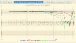
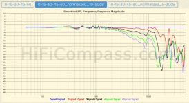
I'm going to do some sims with a higher 2nd order xover and see what happens. I'll report back if there's anything worth sharing. I at least have some off axis measurements made by hificompass for the TC9 and SB26STCN to reference. First one is the SB26STCN and other is the TC9FD18-08.
The reality FOR ME is I haven't met many 25-28mm domes that sound good to my ears at higher playback levels crossed lower than 2.5k 2nd order, especially without a WG. The Morel CAT308 and CAT378 are very good sounding soft domes crossed that low, but they're not cheap. Neither is the neo magnet version CAT408, plus it doesn't sound as good either. Of course i understand that a larger quantity of tweeters playing in an array will have reduced HD compared to a single unit playing at the same SPL.
Another aspect is I'd want to stay clear of crossing in that delicate 1k - 4k band, as that does weird things with vocals, piano and percussive material, sometimes even with a 1st order filter. This is why i usually like 3 way designs with a mid crossed higher than 3.5k. In the case of the TC9, it still sounds great past 4k, so it made sense for me to look at a 2 way line array instead of the traditional fullrange array.
Regarding the choice of tweeter, as I stated before, I wouldn't want to use a typical cheaper compact tweeter, so any other frameless tweeter was out of the question for me - if I didn't like its overall character as a single tweeter in a typical 2 way speaker, I wouldn't like it in larger quantities as an array. For example, the popular little Peerless ring radiator doesn't sound that great to me, especially crossed lower. Many love that tweeter but I don't. It has THD issues under 5k. Some planar tweeters are also a problem for me - usually the cheaper ones don't sound good enougn to be worth using in an array and are usually plagued by rather high 3rd order HD.
I'm going to do some sims with a higher 2nd order xover and see what happens. I'll report back if there's anything worth sharing. I at least have some off axis measurements made by hificompass for the TC9 and SB26STCN to reference. First one is the SB26STCN and other is the TC9FD18-08.
Attachments
The problem in this context is that by having the two drivers both play higher frequencies any lobing will appear in the horizontal plane where it is not particularly benign. Same as a studio monitor turned on it's side, a slight vertical issue becomes a horizontal hole.I know for most oeople that doesn't make much sense ie. not taking advantage of a long line of 25mm tweeters ability to cross much lower with a 1st order filter.
You're probably right about that. Its just something I need to sim whether the tradeoff in horizontal issues is significant enough vs the other problems with lower xover points discussed. I'm just going to keep an open mind and see if the sims present a possible exception to the theory I'm up against.
@fluid Another thing I'm exploring is whether an acoustic lense setup can tame some of the combing and effects of overlap. By that I'm referring to a system of blades covered with thin foam or felt between the individual HF elements to reduce vertical dispersion and therefore HF overlap (sort of what a planar tweeter already does vertically). I used this sort of thing on a tweeter array many years ago and had good success with it. This was of course before computer sims were readily available. What are your thoughts on this idea?
@fluid Another thing I'm exploring is whether an acoustic lense setup can tame some of the combing and effects of overlap. By that I'm referring to a system of blades covered with thin foam or felt between the individual HF elements to reduce vertical dispersion and therefore HF overlap (sort of what a planar tweeter already does vertically). I used this sort of thing on a tweeter array many years ago and had good success with it. This was of course before computer sims were readily available. What are your thoughts on this idea?
With a bit of work and driver level checks it can certainly look much better than my previous sim:

Even though lots more work would be needed to get a better understanding/working model.
However, the lobes will still be there due to the CTC distance used.
If one can influence it with a driver directivity change (using the blades) would be a fun test to find out...
A little inspiration from member FoLLgoTT:
Thanks for checking up on that. Looks somewhat promising. That was my suspicion but as you said the lobing is still a problem. The vertical directivity could be controlled but to what extent without ruining HF driver fidelity. Further down the rabbit hole...
I wonder if there is a way to sim 2 different horizontal driver angles with various crossover points to see what it does with reducing destructive phase interference. There must be an optimal angle at a given xover frequency in relation to the driver directivity, allowing one to hone in on it a bit. Does that make sense?
From my quick calculations, it appears 2 - 2.5k is the desired xover in the horizontal plane with given chassis dimensions and resulting driver spacing. This should reduce issues and place the off axis response dip in the Fletcher Munson "hole" so it doesn't sound weird power response wise. That is of course a relative issue, as it deviates from a desired flat FR.
Sure no reason not to, there are many available parameters to juggle to try and get the best compromise.I'm just going to keep an open mind and see if the sims present a possible exception to the theory I'm up against.
Certainly there is potential in those sort of ideas, I simulated a small lip on the TC9 for wesayso (further on in link I posted before) and it showed a generally positive effect@fluid Another thing I'm exploring is whether an acoustic lense setup can tame some of the combing and effects of overlap. By that I'm referring to a system of blades covered with thin foam or felt between the individual HF elements to reduce vertical dispersion and therefore HF overlap (sort of what a planar tweeter already does vertically). I used this sort of thing on a tweeter array many years ago and had good success with it. This was of course before computer sims were readily available. What are your thoughts on this idea?
https://www.diyaudio.com/community/...ver-full-range-line-array.242171/post-6542350
It requires a more sophisticated simulation than Vituix or measured prototype.
Follgott explored many ideas and for a speaker with narrow vertical and controlled wider horizontal directivity his Quasikoax setup seems like a logical choice much like the fractal design.
https://www.diy-hifi-forum.eu/forum...uasikoax-1&s=151712410586cfda05c39638aa274261
- Home
- Loudspeakers
- Multi-Way
- 2 way TC9 array with SB26STCN