With the value you sent the dissipation on 88 is around 31 watt that is good.
But this is with GZ34?
And leave the stuff as is
Walter
But this is with GZ34?
And leave the stuff as is
Walter
It is with 5U4G.With the value you sent the dissipation on 88 is around 31 watt that is good.
But this is with GZ34?
And leave the stuff as is
Walter
Thanks for all the tips, I will all as is.
Adam

If the 34 give you 20 volt more (p.e.) the increment of the dissipation will be not so much.It is with 5U4G.
Thanks for all the tips, I will all as is.
Adam
Thanks,If the 34 give you 20 volt more (p.e.) the increment of the dissipation will be not so much.
Would using an EL34 require any adjustments?
The diagram states you can exchange no problem, including a number of others, but with my voltage readings I think increasing cathode resistor to 560R - 600R would be more suitable.
Maybe, even adding a switch between 500R for KT88 and 600R for EL34?
Regards
Adam
Note the original Kegger amp had a lower B+ for use with an EL34. You would definitely have to adjust some things to use an EL34.Thanks,
Would using an EL34 require any adjustments?
The diagram states you can exchange no problem, including a number of others, but with my voltage readings I think increasing cathode resistor to 560R - 600R would be more suitable.
Maybe, even adding a switch between 500R for KT88 and 600R for EL34?
Regards
Adam
Kegger Blueglow Amplifier Analysis
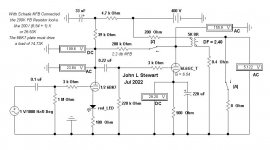
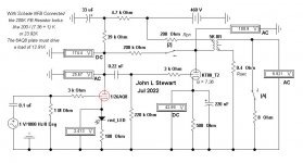
This amplifier is simply another member of a common 2-stage singled ended configuration. It includes the flavor of the day modifications, Schade NFB & a semiconductor in the cathode of the driver tube. I’ve used typical resistance values for the OPT primary & secondary winding resistances. These are not within the FB circuit so that Damping Factor (DF) is limited.
On the schematic the switches ‘A’ & ‘Z’ are used to determine the degree of NFB & the Damping Factor.
The driver must provide signal current to both its plate resistor of 39K & the following grid resistor of 200K. But with Schade NFB there is the added requirement to provide signal current for the 200K FB resistor. The gain of the power stage of 6.54. The power stage inverts so the final result is 200 / (6.54 + 1) K . Now we have a combined parallel combination of 14.73K.
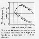
Lower resistance plate loads increase that stage distortion. Not long ago the driver flavor was the mu follower which increases the load seen by the plate. A better way to go. The distortion example shewn is generic, it applies to all common triodes.
Other than it is red, the EI curve of the LED is unknown. Something that happens whenever a randomly sourced LED is used. A vacuum tube has a 3/2s transfer curve while SS Diodes are square Law. That should result in a very interesting distortion family.
The end result, pick whatever flavor of distortion you like. But if the end result is pleasing to the user, that is what matters. All depends more of the speaker & listening room anyway.
With regard to a Website, I believe I have something much better. That being a hands on & technical knowledge of this subject. As quite a few others do on this forum. We can all learn a lot.🙂👍
This amplifier is simply another member of a common 2-stage singled ended configuration. It includes the flavor of the day modifications, Schade NFB & a semiconductor in the cathode of the driver tube. I’ve used typical resistance values for the OPT primary & secondary winding resistances. These are not within the FB circuit so that Damping Factor (DF) is limited.
On the schematic the switches ‘A’ & ‘Z’ are used to determine the degree of NFB & the Damping Factor.
The driver must provide signal current to both its plate resistor of 39K & the following grid resistor of 200K. But with Schade NFB there is the added requirement to provide signal current for the 200K FB resistor. The gain of the power stage of 6.54. The power stage inverts so the final result is 200 / (6.54 + 1) K . Now we have a combined parallel combination of 14.73K.
Lower resistance plate loads increase that stage distortion. Not long ago the driver flavor was the mu follower which increases the load seen by the plate. A better way to go. The distortion example shewn is generic, it applies to all common triodes.
Other than it is red, the EI curve of the LED is unknown. Something that happens whenever a randomly sourced LED is used. A vacuum tube has a 3/2s transfer curve while SS Diodes are square Law. That should result in a very interesting distortion family.
The end result, pick whatever flavor of distortion you like. But if the end result is pleasing to the user, that is what matters. All depends more of the speaker & listening room anyway.
With regard to a Website, I believe I have something much better. That being a hands on & technical knowledge of this subject. As quite a few others do on this forum. We can all learn a lot.🙂👍
Attachments
So in another words: no you haven't built nor have you listened to one, and I can assume you didn't watch the videos showing the measured performance of the finished amplifier either. As far as "hands on", I'm going to listen to folks that have actually put their hands on one building and testing it, rather than speculation. I understand that you like to discount the value of other people's efforts/work, I'm not sure that really does anything positive for our community/hobby.Kegger Blueglow Amplifier Analysis
And all of this unprompted bashing of this website and a contributor was in response to a user asking for help with his project.
Hello John Stewart:
Thank you for the analysis of the circuit. It is very useful and extremely informative.
Thank you for the analysis of the circuit. It is very useful and extremely informative.
Kegger Blueglow Amplifier Analysis
This amplifier is simply another member of a common 2-stage singled ended configuration...
Just to clarify the facts, what you posted isn't the Blueglow KT88 amplifier. None of the voltages match what he published, and this is a great example of what happens when someone doing an "analysis" of something, does so with a bias going into it looking to prove a statement they previously made.That should result in a very interesting distortion family.
The end result, pick whatever flavor of distortion you like....
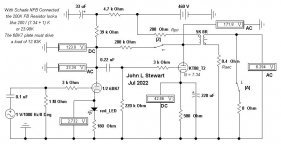
Attached is the actual schematic with measured voltages off the physical amplifier, not some simulation. Also he explains to only use a ecc85 or a 6n1p at the voltages he is running for a driver and how this improves the amp in his video series, and what to do to run the other tubes listed, but that doing so increases the distortion and the amp doesn't sound as good. Also the voltages on the published schematic output tubes are for a KT88 which he also explains in the video series. Again, this "analysis" is using the wrong tubes at different voltages from what a Blueglow KT88 amp is.
I'm sure I can take any amplifier design ever made, and start changing tubes and voltages to get it to sim however badly I wanted it to be.
And FYI the actual distortion numbers of a sample of this amp, running the right tubes at the correct voltages, measured at 1% distortion is making 8W, at 5W is at 0.5% and at 10W it's still under 2%. For a SE amp those are really good numbers, the frequency response is flat and it has a lovely looking square wave. He explains all this in these two videos.
I just wanted to clarify what the measured performance on this "All show no GO" labeled amplifier actually is.
Also to the OP, clearly the voltage increase using the 5AR4 you are talking about is right at the voltages shown for this amp and shouldn't be an issue at all if built to this schematic. As always though, check your voltages!
Last edited:
Also, to add to the measured performance of this 'All show no GO' amp, it sounds excellent.Just to clarify the facts, what you posted isn't the Blueglow KT88 amplifier. None of the voltages match what he published, and this is a great example of what happens when someone doing an "analysis" of something, does so with a bias going into it looking to prove a statement they previously made.
Attached is the actual schematic with measured voltages off the physical amplifier, not some simulation. Also he explains to only use a ecc85 or a 6n1p at the voltages he is running for a driver and how this improves the amp in his video series, and what to do to run the other tubes listed, but that doing so increases the distortion and the amp doesn't sound as good. Also the voltages on the published schematic output tubes are for a KT88 which he also explains in the video series. Again, this "analysis" is using the wrong tubes at different voltages from what a Blueglow KT88 amp is.
I'm sure I can take any amplifier design ever made, and start changing tubes and voltages to get it to sim however badly I wanted it to be.
And FYI the actual distortion numbers of a sample of this amp, running the right tubes at the correct voltages, measured at 1% distortion is making 8W, at 5W is at 0.5% and at 10W it's still under 2%. For a SE amp those are really good numbers, the frequency response is flat and it has a lovely looking square wave. He explains all this in these two videos.
I just wanted to clarify what the measured performance on this "All show no GO" labeled amplifier actually is.
Also to the OP, clearly the voltage increase using the 5AR4 you are talking about is right at the voltages shown for this amp and shouldn't be an issue at all if built to this schematic. As always though, check your voltages!
View attachment 1074332
View attachment 1074333
Indeed, the additional voltage will be at close to those measured by Mark. My B+ with 5U4G is 435v (at the 200uf cap, Mark's is 460v) and 425v at the KT88 plate (Mark's is 450v). So 25v difference between 5U4gb and 5AR4. My secondaries are 750v CT, 375-0-375v so a little less than Mark's Edcor
My circuit is exactly the same, with the only exception of the 5U4gb (of course) and my driver bias LED is IR not red.
Cathode voltage on my 6n1p is 2.5v, KT88 is 41v.
Also, to add to the measured performance of this 'All show no GO' amp, it sounds excellent.
Indeed, the additional voltage will be at close to those measured by Mark. My B+ with 5U4G is 435v (at the 200uf cap, Mark's is 460v) and 425v at the KT88 plate (Mark's is 450v). So 25v difference between 5U4gb and 5AR4. My secondaries are 750v CT, 375-0-375v so a little less than Mark's Edcor
My circuit is exactly the same, with the only exception of the 5U4gb (of course) and my driver bias LED is IR not red.
Cathode voltage on my 6n1p is 2.5v, KT88 is 41v.
If you are using a Hammond PT, I've read their actual measured voltage is a tad higher than advertised. I'd be interested in what the actual AC voltage reading is across the transformer output loaded.
Kegger Blueglow Amp
I’ve gone thru all of your remarks & have some comments & questions.
I got a copy of the amp from the iNet, it appears to be the same as that which you posted.
How does this one differ from yours? Of the many alternative output tubes listed I simply plugged in a 6L6GC. For the driver I used a 6BK7, what did you use? On the Kegger schematic the implication is that any combination of all the tubes they listed are OK. With cathode biasing that is to an extent possible.
The KT88 comes with the same problems that any other beam tetrode or pentode brings with it. How are yours different? FYI, I did build a PP KT88 amp in the Circlotron mode about 20 yrs ago. It easily delivered 50W of audio. At very low distortion. The project was published for all to see in AudioXpress magazine, May 2002. The amp was built as an experimental project, not to look at. Anyone wants a PDF of a more complete copy of the article, pls send me a private msg.
Many designers tell us that SE creates more problems than it solves. In your opinion what are the features of SE that make it better?
I checked the Edcore website for more detail on the specs of the OPT used in your projects. It doesn’t say much. To get a measure of something similar I went to Hammond, their primary inductance is shewn as 50H. I used that in these sims. But nothing listed on leakage inductance that would limit the HF.
And still need to know the primary & secondary winding resistances. Could you measure those & pass them on pls. The secondary resistance will be quite low. To avoid lead & contact resistance errors, pls use a 4-wire method for that.
One volt rms on the front end gets 4 Watts to the OPT output terminals.
What simulation software do you use? And please do read & listen to whoever agrees with you.
Many of the AudioPhile community are nervous about having their amplifier bench tested. Refer to Brosky’s comment.
Throw enough money at a project, anything is possible. This circuit is still another example of a simple 2-stage amplifier, of which there are in infinity of possible combinations.
And why do I need a Website? I’m not in business, you don’t have to buy or listen to me.
But the lurkers here on DIY might be interested in more detail on the Kegger, that is why I posted this. 🙂 👍
Attachments
Kegger Blueglow Amp
How does this one differ from yours? Of the many alternative output tubes listed I simply plugged in a 6L6GC. For the driver I used a 6BK7, what did you use? On the Kegger schematic the implication is that any combination of all the tubes they listed are OK. With cathode biasing that is to an extent possible...
The "Blueglow" final version as posted on his website is setup to run higher voltage than the previous version you created to "analyze" with guestimated transformers etc. Mark's final version is specifically dialed in for a ECC85 and a KT88. Mark explains why he chose the ECC85/KT88 combo and is running higher plate voltage on it in the final video I shared, which obviously you didn't watch or you wouldn't be asking these questions.
Mark also bench tested this amplifier, again in a video I linked: are you now claiming he is faking the results for something he doesn't even sell or profit from? He shows this amplifier hooked up to a scope with both sine waves and square waves running through it, go watch the video I linked and see he isn't "afraid to have it hooked up to a scope" like that comment by Brosky you shared. Do you think that you can sit at your computer and simulate that amplifier better than his actual testing and weeks of listening to the actual built amplifier? Clearly you don't believe the specs he published or you wouldn't be questioning them.
And no, I don't use simulation software, I build amplifiers, bench test them and then listen to them. Not sure why you hijacked this thread to demean someone else's hard work, or what exactly you are even trying to prove here. The OP simply asked a power supply question on his KT88SE amp, a popular one many people have built and praised the sound quality of, and now you are here bragging about some 50W PP amp you published 20 years ago...
And yeah I can live without snarky comments like "And please do read & listen to whoever agrees with you."
I'm done here, have a nice day.
This amp shouldn't even be considered SE. It's operating point is in the normal AB range and this amp actually represents 1/2 of an AB PP amp, but using a SE tranny. The OPT limits the primary current to a lower value than a properly setup KT88 Class A amp would use. The 100ma primary and the high voltage require it to be run on the lower end of the loadline instead of the upper end where a properly setup SE amp would be. The voltages are all wrong for this tube to be used in class A. It is actually so far down the loadline, biased so coldly, that the normal amount of drive signal has to limited to keep the outputs from going into cutoff.
Last edited:
Easy enough to confirm, as the signal is increased the plate current will also increase.
On this one quite a bit, the Q point is too far to the right on the plate family graph.
Not Class A.
On this one quite a bit, the Q point is too far to the right on the plate family graph.
Not Class A.
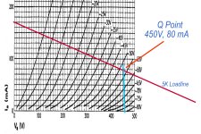
SE KT88 well into Class AB with 460V supply running 80 mA into 5K Loadline.
10V drop in the OPT. 🙂
And if you plot the UL/pentode operating point it's even worse, just a few volts off of the bottom. It's a large tube doing the work of a 6BQ5 and down in the mud part of the Class A. It needs lower B+ and more plate current but that requires a beefier OPT and PT that can provide about 300mA for two tubes and the drivers. The first original circuit this is derived from was closer to that I think. This one is trying to be a power toy that isn't designed right for any of the options. It's like a semi truck being throttled to 25 mph. So it works but you can't get a KT88 worth of power. Testing this at 1kHz for power and clipping/distortion isn't going to show what happens in music with high stroke bass parts that demand high transient power. It'll sound OK at lower volume levels.... It needs bigger iron or at least it should be built as a mono with the right OPT for the job, and correct biasing for that. Lower B+ so it doesn't bust the plate dissipation max. Every data sheet gives examples of single tube operation for best designs.
Last edited:
wow! this is a very interesting analysis of the circuit gentleman. Good for you, the load lines start to tell an intersting story. It does beg the question; why does it get such good reviews by DIY builders? and what would the operating points be to get the best potential from the circuit? ie reasonble power and low distortion.
Thanks for your input
Thanks for your input
wow! this is a very interesting analysis of the circuit gentleman. Good for you, the load lines start to tell an intersting story. It does beg the question; why does it get such good reviews by DIY builders? and what would the operating points be to get the best potential from the circuit? ie reasonble power and low distortion.
Thanks for your input
The UL connection helps, the plate to plate FB helps, the low power demand helps, the good OPT running 25%-30% output helps. The power supply for this specifies a 10H choke. Thats can stay to convert this to a choke input supply and get the B+ in line. But it still needs an different PT and OPT that can give and take higher primary current. ... When the output power is down around 20% of idle current plate wattage, you know somethin' ain't right.
- Home
- Amplifiers
- Tubes / Valves
- KT88SE - Power supply wiring, general query