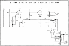
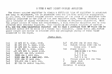
Out of curiosity, I decided to model in LTSpice the direct-coupled 6B4G SET published in Lipman's Practical Amplifier Diagrams (1947), which is identical to Don Garber's Fi 2A3 & Fi X. Lipman does not provide operating voltages, nor have I been able to find any for Don Garber's amps by searching the web.
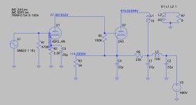
So, I started with a typical operating voltage for the 2A3 (250Vak), using a B+ of 295V. There's supposed to be 45V across R5, which is the grid leak resistor for the 2A3 and plate load resistor for the 6SF5. This results in some pretty unorthodox operating points, with about 15Vak/0.5mA across the 6SF5 and the 2A3 operating at just 5mA. Surely this can't be right?
I've modeled both the original Lipman/Garber circuits as well as Garber's updated one, which replaces the variable resistor R3 and R4 (1K) with a single 5K resistor, and also replaces the 3K cathode resistor on the 6SF5 with a 2.2K (I've verified this change by looking at online gut shots of later Fi 2A3 stereo units). The voltage results are nearly identical in both.
Has anyone built or worked on the Fi 2A3? Does this seem right? Have I messed something up in the model?
Attachments
Jdrouin
You are direct coupling the 6SF5 to the 2A3 so in effect you are stacking the anode voltage of the 6SF5 onto the cathode voltage of the 2A3, hence your power supply B+ will be around 500V not 295V in your model. With a 295V power supply, that's why you are getting 15V on the 6SF5's anode. From memory, try 480V on the anode of the 2A3 and about 185V on the anode of the 6SF5. See who that goes and adjust from there. Remember the Fi circuit is interactive in changing one value affects all the others. Hope this helps.
Regards Ejam

I think your B+ is too low. Lip and power transformer is 650 vct and Garber’s is 750. Try 400 or 450 for the B+.
Huh, OK, thank you. I bumped the voltage source in the model to 480 and now the 6SF5 is about 25Vak/0.8mA and there's about 9mA on the 2A3 plate. The 100K plate load/grid leak resistor has about 90V across it, rather than 45.
I must have made a mistake in LTSpice that I'm just not able to see.
I must have made a mistake in LTSpice that I'm just not able to see.
Attachments
The problem is
Generic triode model: 6SF5_AN
Use 6SF5
.SUBCKT 6SF5 1 2 3 ; P G C;
+{v(1,3)/kp*log(1+exp(kp*(1/mu+v(2,3)/sqrt(kvb+v(1,3)*v(1,3)))))}
re1 7 0 1g
g1 1 3 value= {(pwr(v(7),ex)+pwrs(v(7),ex))/kg1}
rcp 1 3 1g
c1 2 3 {ccg}
c2 1 2 {cgp}
c3 1 3 {ccp}
r1 2 5 {rgi}
d3 5 3 dx
.model dx d(is=1n rs=1 cjo=10pf tt=1n)
.ends
Generic triode model: 6SF5_AN
Use 6SF5
.SUBCKT 6SF5 1 2 3 ; P G C;
- PARAMS: MU=105.88 EX=1.16 KG1=1093.71 KP=992.2 KVB=10000 RGI=2000
- CCG=4.0P CGP=2.4P CCP=3.6P ; ADD .7PF TO ADJACENT PINS; .5 TO OTHERS.
+{v(1,3)/kp*log(1+exp(kp*(1/mu+v(2,3)/sqrt(kvb+v(1,3)*v(1,3)))))}
re1 7 0 1g
g1 1 3 value= {(pwr(v(7),ex)+pwrs(v(7),ex))/kg1}
rcp 1 3 1g
c1 2 3 {ccg}
c2 1 2 {cgp}
c3 1 3 {ccp}
r1 2 5 {rgi}
d3 5 3 dx
.model dx d(is=1n rs=1 cjo=10pf tt=1n)
.ends
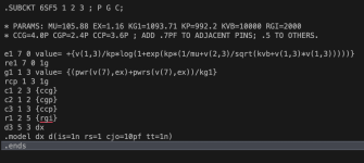
I see, in my post #7, the "+" got translated to "*" !! RGI=2000.
See post #1670
https://www.diyaudio.com/community/threads/vacuum-tube-spice-models.243950/page-84
for the authentic copy of the model.
See post #1670
https://www.diyaudio.com/community/threads/vacuum-tube-spice-models.243950/page-84
for the authentic copy of the model.
It's the variable R3-R4 combination. (R3 in yours) . Lower the R value and everything starts to work. 2a3 Vp just under max. In the real thing there'd be series resistance in L1 and L3 (none in sim) so it would be lower.

From the 62mA out of U2 0,55mA goes to U1 leaving 61,45mA for R3. And 3k x 61,45 = 184,35V.It's the variable R3-R4 combination. (R3 in yours) . Lower the R value and everything starts to work. 2a3 Vp just under max. In the real thing there'd be series resistance in L1 and L3 (none in sim) so it would F
So, who needs R6 ?
Mona

Yes , I thought so too. I questioned whether Garber's circuit would have been exactly the same and I would never have thought of it myself, but so what? (and directdriver's posted version doesn't agree with the OP's Fi "Upgrade" sketch.So, who needs R6 ?
Mona
Lipman's circuit is still interesting. He was certainly thinking something when he did it this way. R6 appears to use the PS filter to make a stable bias supply and does it also make a little feedback?
R6 makes the cathode voltage of U2 less dependent of U2's current.I think that 's a disadvantage.
Suppose U2 starts to draw more current, it's cathode goes up and so does the anode of U1. With more voltage on his anode U1 pulls more current and the voltage on R5 , witch is the negative grid voltage of U2,goes up too thereby lowering the U2 current. Sort of stabilising effect.
Mona
Suppose U2 starts to draw more current, it's cathode goes up and so does the anode of U1. With more voltage on his anode U1 pulls more current and the voltage on R5 , witch is the negative grid voltage of U2,goes up too thereby lowering the U2 current. Sort of stabilising effect.
Mona
Thanks to fossa for the correct 6SF5 model file link. I've got it working now and the results are much closer to the expected behavior.
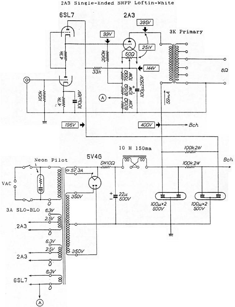
Thanks to directdriver for the additional DC 2A3 schematics. I had collected those but didn't think to compare them to Garber/Lipman. That was very helpful, in large part because all the circuits I've built or modeled in the past are cap coupled, so the output tube cathode is usually connected to ground by a self-bias resistor. Even though in Garber/Lipman I was looking at the + side of the PS rail running directly under the 2A3 cathode, it still didn't dawn on me how much higher the plate voltage would need to be above that.
At any rate, with comparative schemos and working software, I've been able to play around and see how the components of the circuit interact with one another. It's much less modular than a traditional cap-coupled design because, as was said earlier, everything is so interdependent, as ketje and Hearinspace's exchange demonstrates.
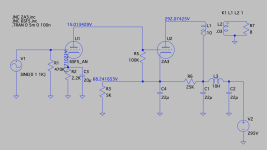
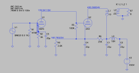
Here's a working version that's a little closer to the original circuit with 3K on the 6SF5 cathode. With a B+ of 450V and R3 at 2.6K, we get close to the typical operating values for both the 6SF5 and 2A3.
Thanks to directdriver for the additional DC 2A3 schematics. I had collected those but didn't think to compare them to Garber/Lipman. That was very helpful, in large part because all the circuits I've built or modeled in the past are cap coupled, so the output tube cathode is usually connected to ground by a self-bias resistor. Even though in Garber/Lipman I was looking at the + side of the PS rail running directly under the 2A3 cathode, it still didn't dawn on me how much higher the plate voltage would need to be above that.
At any rate, with comparative schemos and working software, I've been able to play around and see how the components of the circuit interact with one another. It's much less modular than a traditional cap-coupled design because, as was said earlier, everything is so interdependent, as ketje and Hearinspace's exchange demonstrates.
Here's a working version that's a little closer to the original circuit with 3K on the 6SF5 cathode. With a B+ of 450V and R3 at 2.6K, we get close to the typical operating values for both the 6SF5 and 2A3.
- 6SF5 -- 138Vak, 0.4mA
- 2A3 -- 248vAk, 58mA
- R5 -- 43V
- Input sensitivity -- about 1.25V
Attachments
jdrouinThanks to fossa for the correct 6SF5 model file link. I've got it working now and the results are much closer to the expected behavior.
Thanks to directdriver for the additional DC 2A3 schematics. I had collected those but didn't think to compare them to Garber/Lipman. That was very helpful, in large part because all the circuits I've built or modeled in the past are cap coupled, so the output tube cathode is usually connected to ground by a self-bias resistor. Even though in Garber/Lipman I was looking at the + side of the PS rail running directly under the 2A3 cathode, it still didn't dawn on me how much higher the plate voltage would need to be above that.
At any rate, with comparative schemos and working software, I've been able to play around and see how the components of the circuit interact with one another. It's much less modular than a traditional cap-coupled design because, as was said earlier, everything is so interdependent, as ketje and Hearinspace's exchange demonstrates.
Here's a working version that's a little closer to the original circuit with 3K on the 6SF5 cathode. With a B+ of 450V and R3 at 2.6K, we get close to the typical operating values for both the 6SF5 and 2A3.
- 6SF5 -- 138Vak, 0.4mA
- 2A3 -- 248vAk, 58mA
- R5 -- 43V
- Input sensitivity -- about 1.25V
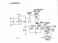
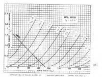
Spice gotta love it, works out everything for you except the obvious, in that circuit, it will compress badly as there is not enough headroom in the 6SF5 driver. Old school: 6SF5 curves attached with the Spice calculated operating point giving a theoretical maximum of 42.9V swing in the negative (linear for 30V at best) - result lots of second harmonic and I mean lots.
Attachments
Thanks, Ejam. Can you explain to me what you mean by compression? I’ve not seen that term in this context before. Also, why would the 6SF5 run that way result in lots of second order harmonics?
I’m interested in understanding how tube operation affects harmonics so as to control aspects of voicing (or so people call it), soundstage & imaging, etc.
I’m interested in understanding how tube operation affects harmonics so as to control aspects of voicing (or so people call it), soundstage & imaging, etc.
In an attempt to clear up the problem with the bad version 6SF5 Ayumi model floating around, member jazbo8 posted a correction for that model in the LTspice models thread. This is the corrected one, which should work.
***** CORRECTED MODEL BY jazbo8 *****
*
.SUBCKT 6SF5_AN A G K
- Generic triode model: 6SF5_AN
- Copyright 2003--2008 by Ayumi Nakabayashi, All rights reserved.
- Version 3.10, Generated on Sat Dec 13 18:55:08 2014
- Plate
- | Grid
- | | Cathode
- | | |
BGG GG 0 V=V(G,K)+0.4894906
BM1 M1 0 V=(0.0018194781*(URAMP(V(A,K))+1e-10))**-0.29474303
BM2 M2 0 V=(0.83577425*(URAMP(V(GG)+URAMP(V(A,K))/90.259814)+1e-10))**1.794743
BP P 0 V=0.00099890055*(URAMP(V(GG)+URAMP(V(A,K))/107.99545)+1e-10)**1.5
BIK IK 0 V=U(V(GG))*V(P)+(1-U(V(GG)))*0.00061836196*V(M1)*V(M2)
BIG IG 0 V=0.00049945028*URAMP(V(G,K))*1.5(URAMP(V(G,K))/(URAMP(V(A,K))+URAMP(V(G,K)))*1.2+0.4)
BIAK A K I=URAMP(V(IK,IG)-URAMP(V(IK,IG)-(0.00051335655*URAMP(V(A,K))**1.5)))+1e-10*V(A,K)
BIGK G K I=V(IG)
* CAPS
CGA G A 2.4p
CGK G K 4p
CAK A K 3.6p
.ENDS
jdrouinThanks, Ejam. Can you explain to me what you mean by compression? I’ve not seen that term in this context before. Also, why would the 6SF5 run that way result in lots of second order harmonics?
I’m interested in understanding how tube operation affects harmonics so as to control aspects of voicing (or so people call it), soundstage & imaging, etc.
Sorry for the late reply, am on the other side of the world, so your awake, am asleep and vice-versa. Compression is merely a term to describe the bunching of the curves to the right of the operating point. If you look at the right side curves, you'll see them getting closer together and to the left of the operating point, further apart. Now if the curves were evenly spaced, then you would have no distortion. However in our case as the musical signal moves along the loadline, left and right, it for a better term compresses, as the signal becomes more negative and, expands as it becomes more positive, hence the generation of distortion and in the case of tubes mostly second harmonic distortion. Where it becomes particularly bad is when the Vgk curves rapidly change curvature when operating currents are low. You'll see below 0.2mA for the 6SF5 the curves bend greatly and above 0.5mA they straighten and the spacing becomes more uniform. So when choosing an operating point, best to avoid that non-linear region. That is the standard engineering approach and quite sound. Now in the black arts of tube design, this added distortion maybe used to advantage as the 6SF5 inverts the signal (and its distortion) being a common cathode stage. Now the 2A3 generates distortion as well. The trick is to get an input tube that has a distortion profile matching the output tube's. By adding the inverted distortion to the distortion, hey presto they cancel, at least in theory. Perhaps this is what Don Garber found with the 6SF5. The 6SF5 is similar to the 12AX7, 6SL7. 12BZ7 tubes in distortion profile and I've had no luck with them using a 2A3. Mine you I haven't tried every combination and no doubt someone on diyaudio will pull a rabbit out of a hat. I can say that the 12AT7 and the 6J6 worked this magic with the 2A3. Anyway, enough from me, hope this helps. For what its worth, I have never been able to make Garber's amp design work, always thought there were deliberate mistakes in the component values to throw copiers off.
- Home
- Amplifiers
- Tubes / Valves
- Operating Points of Fi 2A3 / 3 Tube 3 Watt Direct Coupled Amplifier (Lipman)