Hello,
Some web research lead me to 2 documents I would like to share.
The first one is the web page Does Size Really Matter When it Comes to DML Speakers? At the end of the page, there is a calculator saying to link the lowest frequency for a DML to the panel dimension. Having a look to the page code, the formulas are :
Does somebody have an experience about that, an idea of the origin and the applicability to DML (I have doubt...)?
The second document is Development of panel loudspeaker system: Design, evaluation and enhancement. In chapter IV there is a design guide. Most of the items make sense following what I tested and what we have shared here.
In particular, it mentions the relation to E/rho^3 as a driver of efficiency.
What is more unusual is the proposal for the suspension in 8 points in the corner (see extract below)
Does somebody experiment such suspension?
Christian

Some web research lead me to 2 documents I would like to share.
The first one is the web page Does Size Really Matter When it Comes to DML Speakers? At the end of the page, there is a calculator saying to link the lowest frequency for a DML to the panel dimension. Having a look to the page code, the formulas are :
- csound = sound speed m/s, H = panel height m, W = panel width m; hypo = hypotenuse = (H² + W²)^0.5
- lowfreq = 0.7 * csound / hypo in Hz
- lowestaudiblefreq = lowfreq - 107*H*W in Hz, H and W in m
Does somebody have an experience about that, an idea of the origin and the applicability to DML (I have doubt...)?
The second document is Development of panel loudspeaker system: Design, evaluation and enhancement. In chapter IV there is a design guide. Most of the items make sense following what I tested and what we have shared here.
In particular, it mentions the relation to E/rho^3 as a driver of efficiency.
What is more unusual is the proposal for the suspension in 8 points in the corner (see extract below)
Does somebody experiment such suspension?
Christian

Christian,Hello,
Some web research lead me to 2 documents I would like to share.
The first one is the web page Does Size Really Matter When it Comes to DML Speakers? At the end of the page, there is a calculator saying to link the lowest frequency for a DML to the panel dimension. Having a look to the page code, the formulas are :
Original formulas in the code are in feet (if case some wants to have a look in the page code)
- csound = sound speed m/s, H = panel height m, W = panel width m; hypo = hypotenuse = (H² + W²)^0.5
- lowfreq = 0.7 * csound / hypo in Hz
- lowestaudiblefreq = lowfreq - 107*H*W in Hz, H and W in m
Does somebody have an experience about that, an idea of the origin and the applicability to DML (I have doubt...)?
The second document is Development of panel loudspeaker system: Design, evaluation and enhancement. In chapter IV there is a design guide. Most of the items make sense following what I tested and what we have shared here.
In particular, it mentions the relation to E/rho^3 as a driver of efficiency.
What is more unusual is the proposal for the suspension in 8 points in the corner (see extract below)
Does somebody experiment such suspension?
Christian
The first link (Does Size Matter....) is basically worthless. If the formulas do not include panel thickness or elastic modulus, there is no way they could be meaningful for anything other than the exact panel material and thickness that the author used (if that).
The "Bai" article you linked is one with which I am very familiar. I think there is much to learn from it, if you are able to decipher it. It's on the top of my stack of good DML papers and I have read it many times.
In fact, in the spreadsheet I shared with you, my calculation for panel area required (for a given lowest frequency) is based on eqn 23 from this very paper.
I must admit, that there is much I don't understand, but the reference to (E/rho)^3 in eqn 24 certainly caught my attention and confirmed for me the significance of this parameter for efficiency.
There are two things I find a bit odd from this paper. One is where in "step 2" with reference to eqn 23, where they suggest choosing either "small D or small mu" for a small panel, presumably to achieve a sufficiently low fundamental frequency. I think they meant to say "small D or large (not small) mu" since small mu would have the opposite effect of small D. I suspect that "small mu" was a typo. Let me know if you think I missed something there.
Secondly, I think it is a bit odd that in step 3/ eqn 24, they seem to be suggesting that one can select E and rho independently of D and mu, which appear in the same equation. But obviously, D and mu depend directly on E and rho so that is a bit misleading or at least confusing. My own interpretation of that equation is that they are trying to show that for a given fundamental frequency, the lowest impedance, and hence greatest efficiency, is when (E/rho^3) is as large as possible.
Concerning the issue of support points: I must admit that I missed that detail in previous readings. Curiously fig 6a seems to be showing only 4 support points, while 6b clearly shows 8. Also, fig 6b seems to be showing support points substantially inboard of the perimeter, but when you look at the dimensions they are really only 3 mm from the edge, so they are effectively on (not really inside) the perimeter. The logic they mention in step 5 of putting the supports where the most nodal lines cross seems to be reasonable advice, and basically consistent with the NXT philosophy. But I think they missed the fact that you can favorably influence the distribution (along the frequency axis) of modes by selecting particular panel aspect ratios and support points.
Finally, I have to add that I was very pleased to see that this author acknowledged the lectures of Dr William Thompson Jr of ARL/PSU. I was a student of Dr. Thompson for at least one undergraduate course while I was at PSU, but for the life of me I can't recall which course it was. It was over 35 years ago, so I hope I can be excused for that.
Eric
I see tech ingredients have had a new video of dml panels , some might find it interesting.
Steve.
Hello EricChristian,
The first link (Does Size Matter....) is basically worthless. If the formulas do not include panel thickness or elastic modulus, there is no way they could be meaningful for anything other than the exact panel material and thickness that the author used (if that).
The "Bai" article you linked is one with which I am very familiar. I think there is much to learn from it, if you are able to decipher it. It's on the top of my stack of good DML papers and I have read it many times.
In fact, in the spreadsheet I shared with you, my calculation for panel area required (for a given lowest frequency) is based on eqn 23 from this very paper.
I must admit, that there is much I don't understand, but the reference to (E/rho)^3 in eqn 24 certainly caught my attention and confirmed for me the significance of this parameter for efficiency.
There are two things I find a bit odd from this paper. One is where in "step 2" with reference to eqn 23, where they suggest choosing either "small D or small mu" for a small panel, presumably to achieve a sufficiently low fundamental frequency. I think they meant to say "small D or large (not small) mu" since small mu would have the opposite effect of small D. I suspect that "small mu" was a typo. Let me know if you think I missed something there.
Secondly, I think it is a bit odd that in step 3/ eqn 24, they seem to be suggesting that one can select E and rho independently of D and mu, which appear in the same equation. But obviously, D and mu depend directly on E and rho so that is a bit misleading or at least confusing. My own interpretation of that equation is that they are trying to show that for a given fundamental frequency, the lowest impedance, and hence greatest efficiency, is when (E/rho^3) is as large as possible.
Concerning the issue of support points: I must admit that I missed that detail in previous readings. Curiously fig 6a seems to be showing only 4 support points, while 6b clearly shows 8. Also, fig 6b seems to be showing support points substantially inboard of the perimeter, but when you look at the dimensions they are really only 3 mm from the edge, so they are effectively on (not really inside) the perimeter. The logic they mention in step 5 of putting the supports where the most nodal lines cross seems to be reasonable advice, and basically consistent with the NXT philosophy. But I think they missed the fact that you can favorably influence the distribution (along the frequency axis) of modes by selecting particular panel aspect ratios and support points.
Finally, I have to add that I was very pleased to see that this author acknowledged the lectures of Dr William Thompson Jr of ARL/PSU. I was a student of Dr. Thompson for at least one undergraduate course while I was at PSU, but for the life of me I can't recall which course it was. It was over 35 years ago, so I hope I can be excused for that.
Eric
For the first link, yes, no utility like that. I keep it somewhere in the background as I am still wondering what happens at the first resonance frequency between the front and rear wave. I would expect some cancellation but I haven't found any evidence of that up to now.
The "Bai article" is a good synthesis of the physics of DML.
What is strange to me with this kind of academic paper is they seem mastering the theory but the applications seem not being of the premium quality (do they listen music with?). There might be a constraint on such research like the expected area of application : for this paper loudspeaker for computer?
I agree there is probably an error in "small D, small µ"
By letting D and µ they haven't pushed enough the variable change. You are right, replacing them by f0 would have given a clearer expression. f0 is almost fixed at the beginning of the design in a range like 50Hz to 150Hz.
It is strange also to have chosen a so high f0 (almost 300Hz) with no mention to the rule of thumb of 2.5 f0 for the real bandwith. Like id the dimensions where a constraint with no better material to go down. Despite that, the fig12b shows a response going down 200Hz. Is there a trick like an effect of the exciter that might lower the natural plate resonance?
I try to use the kind of electrical model they give but with no real success. It seems too simplified of to be used with a mechanical model.
I think there is also an interesting advice for the exciter going in the way discussed in this thread : high BL, low inductance.
They mention the aspect ratio in the step 4 by distinguishing the modes in one direction and in the second direction. The advice is to interleaved them but there is no practical values.
About the suspension, there are no practical information; just the value of the compliance which for me at the moment has no meaning (is it a weak or strong spring, I don't know). It gives probably an additional configuration to test.
At the moment, if I have some direction to go for the panel based on plywood or sandwich, I have no clear direction for the suspension. The full foam surrounding I have in my plywood panel seems not too bad but without any link to physical models.
So I don't know if I'll do it but this design guide gives ideas to write something (not an academic paper, more something that make bridge between full handcraft and physics, some 1st steps of engineering...).
Christian
Thank you SteveI see tech ingredients have had a new video of dml panels , some might find it interesting.
Steve.
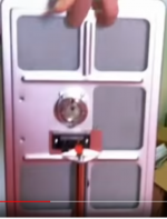
I had a quick look on this video... not really interested by the overall installation but more the detail of the panels. So what I see :
- Materials : polystyrene (seems XPS) and acoustic tiles => acoustic tile is something I haven't seen here. Somebody already tested it?
- The system is a 5.1, 10 panels running by 2 in series plus a sub
- Short 2 string hanging with some holes with tubes or metal plus epoxy for a hook
- Epoxy reinforcement at the exciter (50 to 60ml) apply on the panel in horizontal position (like a liquid?). This perhaps the new think for me as I follow them time to time
- Exciter DAEX32QMB-4 Dayton Audio located at 40% (classical 2/5) and stick thanks to the original double side tape from the exciter (no spine, no system for hanging the exciter)
- The ratio of the panel is a little bit less than 2:1. I evaluate it at 1.95:1
Christian
This is the soundright I tried to post before the homepage doesn't seem to work anymore, so I presume they are not operating anymore.
But there is usefull information and an article by Peter mapp.
Steve
https://www.google.com/url?sa=t&sou...UQFnoECAUQAQ&usg=AOvVaw0jl4JtgvGAoRpU6L70ifzs
But there is usefull information and an article by Peter mapp.
Steve
https://www.google.com/url?sa=t&sou...UQFnoECAUQAQ&usg=AOvVaw0jl4JtgvGAoRpU6L70ifzs
Last edited:
Which technical information about those panels? materials, suspension...This is the soundright I tried to post before the homepage doesn't seem to work anymore, so I presume they are not operating anymore.
But there is usefull information and an article by Peter mapp.
Steve
https://www.google.com/url?sa=t&sou...UQFnoECAUQAQ&usg=AOvVaw0jl4JtgvGAoRpU6L70ifzs
They do not talk about how the panels are built.Which technical information about those panels? materials, suspension...
I am sure I have seen this panel built by various companies before, mainly for pro or lecture use?
I found it interesting how they were integrating with subs.
There are a few interesting pdf files and papers.
Steve.
This was posted 10 years ago by another company but as I have said , I have seen others producing this panel.
Who originally produced this I do not know ?
Steve.
Who originally produced this I do not know ?
Steve.
Last edited:
Hello Steve,This was posted 10 years ago by another company but as I have said , I have seen others producing this panel.
Who originally produced this I do not know ?
Steve.
There are some information from this video
the large panel
- aspect ratio is about 1.28
- the panel material is printable, light grey with a honeycomb core. An idea of the possible material?
- the frame seems to have a U cross section
- exciter position : 0.43xshort side, 0.47xlong side (less precise on the long side because of the video angle)
- the exciters seem to have a conical vent at the back
- 1/6 of the rear area is
Attachments
@spedge
Steve, I had a look around honeycomb core printable polypro and found the Akylite product. It is not a honeycomb but a bubble core.
450g/m² in 2.5mm thickness, 600g/m² for the 2.9mm.
Is it in the list of material you are testing with JohnnoG?
Compare to the flute version, the stiffness is probably more homogeneous according to the direction.
Christian
I found this ,which is about one of the manufacturers I remember.
https://forums.prosoundweb.com/inde...PSESSID=j8tma1v2h34974mgoesaet3s1g#msg1442595
https://forums.prosoundweb.com/inde...PSESSID=j8tma1v2h34974mgoesaet3s1g#msg1442595
Christian.
No I have not seen this Akylite material .
JohnnoG is only sending fluted proplex I believe.
I did have a quick look for Akylite but could only find it in printed form, which was expensive.
As for panel sizes, how does johnnoGs 2ft proplex panels with at least 40hz output, with my exciters, equate to panel theory ?
Steve.
I was thinking of putting my small crate ply in a frame similar to the canvas panel, but using some sort of tape as a surround ,a sort of open backed bmr, but not trying to promote the BMR ?
Then compare the two panels.
Hopefully this wouldn't take too much effort.
Steve.
Then compare the two panels.
Hopefully this wouldn't take too much effort.
Steve.
Eucy,Hi Eric - Just noticed this comment . Your approach with the stiffness ratios on high aspect panels is diametrically opposed to mine - I've explained previously (or tried to) that I firmly believe that the vertical/lateral stiffness ratios should be in proportion to the dimensions (within practical limits), particularly if the sides are supported, so I would be very interested to hear how you have arrived at your conclusions.
Thanks
Eucy
Finally I can reply to your question.
What I believe is that for a panel with high aspect ratio (say >3:1), and that is constrained around the perimeter (simple/hinged or clamped), there is an advantage when stiffness of the panel in the long direction is lower than the stiffness of the panel in the short direction. I say this for the following reasons. As I explained here:
https://www.diyaudio.com/community/...s-as-a-full-range-speaker.272576/post-6999886
the advantage of a high aspect ratio panel with constrained edges is that the first several natural frequencies are more closely and more regularly spaced than for lower aspect ratio panels. This is advantageous, as it increases the possibility for a relatively smooth frequency response at the low frequency end (say roughly the first 3 octaves above the panel's fundamental). With irregular spacing of the natural frequencies, there will be dips in the frequency response in the regions between two widely spaced natural frequencies, and spikes in the frequency response where two or more natural frequencies are close together. But regular spacing of the natural frequencies reduces the possibility of such large dips and spikes.
The advantage of having the long direction of the panel correspond with the direction of lower stiffness is that such an arrangement further reduces the spacing of the lowest natural frequencies, and hence (presumably) reduces the likelihood of dips in the frequency response in the gaps between them.
Below is a table showing the frequencies of the lowest four odd,odd modes of vibration, for three virtually identical panels, but with different elastic moduli (and hence stiffness) in the two directions. All calculations were performed using the LISA Finite Element modelling software. In all three cases, the panel is approximately 1.2 m x 0.3 m (4:1 aspect ratio) with the "x" direction corresponding to the long dimension of the panel, and "y" the short direction, although I adjusted the dimensions slightly to make the fundamental frequency identical at 100 Hz for each case, to allow easier comparison. But I maintained the same aspect ratio (4:1) for every case. Also, since I used the same stiffness in the short direction for all three cases (Ey), only small a small adjustment in size was required to equalize the fundamental frequencies at 100 Hz.
Case 1 is the quasi-isoptropic case in which the stiffness in both directions is the same. In case 2, I increased the modulus in the x direction by a factor of four, as your proposed rule would suggest (if I understand correctly). But note in that case that the gaps between each of the successive modes is almost twice the gap for the quasi-isotropic case. For example the gap between the 1,1 and 1,3 modes is only 32 hz for the quasi-isotropic case and 62 Hz when the modulus in the long direction is fourfold higher. But reducing the modulus in the long direction (Case 3) has the opposite effect, and reduces the gap between the 1,1 and 1,3 modes to only 22 Hz. Likewise the steps between all the successive modes are closer when the modulus in the long direction is lower than the modulus in the short direction. Therefore, I'm inclined to think that having the lower modulus in the long direction is preferred for this particular type of panel. In effect, aligning the lower modulus direction with the long direction of the panel makes it act like a slightly higher aspect ratio panel.
Hope that explanation helps,
Eric
Hi EricEucy,
Finally I can reply to your question.
What I believe is that for a panel with high aspect ratio (say >3:1), and that is constrained around the perimeter (simple/hinged or clamped), there is an advantage when stiffness of the panel in the long direction is lower than the stiffness of the panel in the short direction. I say this for the following reasons. As I explained here:
https://www.diyaudio.com/community/...s-as-a-full-range-speaker.272576/post-6999886
the advantage of a high aspect ratio panel with constrained edges is that the first several natural frequencies are more closely and more regularly spaced than for lower aspect ratio panels. This is advantageous, as it increases the possibility for a relatively smooth frequency response at the low frequency end (say roughly the first 3 octaves above the panel's fundamental). With irregular spacing of the natural frequencies, there will be dips in the frequency response in the regions between two widely spaced natural frequencies, and spikes in the frequency response where two or more natural frequencies are close together. But regular spacing of the natural frequencies reduces the possibility of such large dips and spikes.
The advantage of having the long direction of the panel correspond with the direction of lower stiffness is that such an arrangement further reduces the spacing of the lowest natural frequencies, and hence (presumably) reduces the likelihood of dips in the frequency response in the gaps between them.
Below is a table showing the frequencies of the lowest four odd,odd modes of vibration, for three virtually identical panels, but with different elastic moduli (and hence stiffness) in the two directions. All calculations were performed using the LISA Finite Element modelling software. In all three cases, the panel is approximately 1.2 m x 0.3 m (4:1 aspect ratio) with the "x" direction corresponding to the long dimension of the panel, and "y" the short direction, although I adjusted the dimensions slightly to make the fundamental frequency identical at 100 Hz for each case, to allow easier comparison. But I maintained the same aspect ratio (4:1) for every case. Also, since I used the same stiffness in the short direction for all three cases (Ey), only small a small adjustment in size was required to equalize the fundamental frequencies at 100 Hz.
Case 1 is the quasi-isoptropic case in which the stiffness in both directions is the same. In case 2, I increased the modulus in the x direction by a factor of four, as your proposed rule would suggest (if I understand correctly). But note in that case that the gaps between each of the successive modes is almost twice the gap for the quasi-isotropic case. For example the gap between the 1,1 and 1,3 modes is only 32 hz for the quasi-isotropic case and 62 Hz when the modulus in the long direction is fourfold higher. But reducing the modulus in the long direction (Case 3) has the opposite effect, and reduces the gap between the 1,1 and 1,3 modes to only 22 Hz. Likewise the steps between all the successive modes are closer when the modulus in the long direction is lower than the modulus in the short direction. Therefore, I'm inclined to think that having the lower modulus in the long direction is preferred for this particular type of panel. In effect, aligning the lower modulus direction with the long direction of the panel makes it act like a slightly higher aspect ratio panel.
View attachment 1069448
Hope that explanation helps,
Eric
Thanks for the reply
A few comments :
1/ Clarifying my stiffnesses...My aim is to get compatible deflections in the XY directions. Given that a static ∆ under a point load is a fn of L^2, a span ratio of 4:1 would require the Y stiffness to be 1/16th that of the X. It happens that El/Et for most panel timbers is approx 20. So providing the panel is stable at the selected thickness, that aim is met.
Plywood is a bit different but with 3 ply, the central longitudinal layer does little to provide transverse stiffness, so near enough for me.
I have been using a 3:1 ratio so I've already deviated from my aim, but the principle is still in play.
2/ I think we're probably aiming at different things. You're trying to equalise the gaps between the eigenfrequencies, and I'm trying to push the lowest one back down the axis. I'd be very interested to see what the unadjusted f0 is for a 4:1 panel with a 16:1 stiffness ratio and S/S long sides..(and clamped sides for that matter.)
And a 3:1 panel with a 10:1 stiffness ratio...just while you're at it LOL
3/ Is it actually better to have the reduced spacing? We're talking the difference between driven frequency response and resonant frequency excitation. Throw in harmonics and we have a very complicated picture.
4/ My current 3:1 panel build goes down to 60hz, tops out close to 20khz, has 5dB peaks @90 and 200, a dip @150, and is very well behaved outside those 3 spots. So would additional transverse stiffness help at those frequencies?...don't know.
I tested EQ-ing out the bumps and the difference between EQ and no EQ at those points is basically inaudible ( to me at least).
When I get home and find time I'll try and isolate the peak locations by Chladni testing and see if I can damp them down. The dip may be tougher to deal with unless damping the peaks also fixes the dip.
I was mulling over doing some FEA so maybe I'll get to that also. Just not entirely convinced that models can be complex enough to mimic real world testing
Eucy
Eucy,Hi Eric
Thanks for the reply
A few comments :
1/ Clarifying my stiffnesses...My aim is to get compatible deflections in the XY directions. Given that a static ∆ under a point load is a fn of L^2, a span ratio of 4:1 would require the Y stiffness to be 1/16th that of the X. It happens that El/Et for most panel timbers is approx 20. So providing the panel is stable at the selected thickness, that aim is met.
Plywood is a bit different but with 3 ply, the central longitudinal layer does little to provide transverse stiffness, so near enough for me.
I have been using a 3:1 ratio so I've already deviated from my aim, but the principle is still in play.
2/ I think we're probably aiming at different things. You're trying to equalise the gaps between the eigenfrequencies, and I'm trying to push the lowest one back down the axis. I'd be very interested to see what the unadjusted f0 is for a 4:1 panel with a 16:1 stiffness ratio and S/S long sides..(and clamped sides for that matter.)
And a 3:1 panel with a 10:1 stiffness ratio...just while you're at it LOL
3/ Is it actually better to have the reduced spacing? We're talking the difference between driven frequency response and resonant frequency excitation. Throw in harmonics and we have a very complicated picture.
4/ My current 3:1 panel build goes down to 60hz, tops out close to 20khz, has 5dB peaks @90 and 200, a dip @150, and is very well behaved outside those 3 spots. So would additional transverse stiffness help at those frequencies?...don't know.
I tested EQ-ing out the bumps and the difference between EQ and no EQ at those points is basically inaudible ( to me at least).
When I get home and find time I'll try and isolate the peak locations by Chladni testing and see if I can damp them down. The dip may be tougher to deal with unless damping the peaks also fixes the dip.
I was mulling over doing some FEA so maybe I'll get to that also. Just not entirely convinced that models can be complex enough to mimic real world testing
Eucy
If I understand correctly, what you are suggesting is to roughly match the effective stiffnesses (including the length effect) in the two directions, yes? But what I don't understand is what you beleive is the effect of that matching, and why would it be advantageous?
Or is it rather that you have observed satisfactory perfomance when the stiffness in the two directions seems matched, and have inferred from that experience that it might be a useful rule of thumb?
Static deflections are usually functions of L^3 rather than L^2 aren't they? PL^3/3EI for cantilever beam, and PL^3/48EI for simply supported beam? Are you thinking of something else that I'm forgetting/missing?
The simplest method of pushing the fundamental down the axis is to lengthen the short side (or both sides), but I suspect you know that. I can model some of your proposed designs. It's easy to model, but a little harder to share all the results.
I am convinced that having the natural frequencies close and regularly spaced is a good thing. One of the main points in the NXT patents is placing the exciter in the position that excites the most modes (more modes means closer modes), and selecting an aspect ratio so that the natural frequencies are "interleaved", that is to say regularly spaced. So I don't think I am alone in that belief. That said, I can't say how close is close enough. I feel certain it depends on the damping, both within the panel and at the perimeter. Generally, I have had pretty good success with a panel aspect ratio approaching 4. And I've had decent success even when the stiffness in both directions is roughly comparable. So while I say there may be some advantage if the stiffness is lower in the long direction, it doesn't have to be so, as long as the panel aspect ratio is high enough.
Incidentally, I realized only recently that the NXT patents also recognized this feature of panels with high aspect ratio, in this patent:
https://patentimages.storage.googleapis.com/3c/12/36/2e7517cb3f2ffc/WO1999052324A1.pdf
In the above passage they are actually talking about panels with clamped edges, but hinged/simple edges provide similar closely spaced natural frequencies.
If you can get the Chladni approach to work, that would be cool. I've had much better success identifying the natural frequencies of my panels using "tap testing" as I described here:
https://www.diyaudio.com/community/...r-dml-design-and-analysis.383567/post-6954047
But it's very helpful to be using FEA in combination with the tap testing, in order to know where the nodes and antinodes would like be for each mode you want to identify.
I do encourage you to try FEA. But I don't claim it will give you all the answers. My FEA will predict pretty well the natural frequencies of my panels, and help me estimate their elastic constants, but it doesn't do any more than that. It doesn't tell me which modes will radiate with the most power, and it won't tell me how they all interact. It's just one piece of the puzzle.
Eric
I'd be very interested to see what the unadjusted f0 is for a 4:1 panel with a 16:1 stiffness ratio and S/S long sides..(and clamped sides for that matter.)
And a 3:1 panel with a 10:1 stiffness ratio...just while you're at it LOL
Eucy
Eucy,
What actual panel dimensions would you be interested in? Lateral dimensions and thickness? Any idea of moduli and density? For moduli I would choose maybe 10 GPa with the grain and 10/16 = 0.625 Gpa against the grain. And a density of about 0.5 g/cm3 unless you prefer other.
In my previous models i was not considering that you were using single ply planks without crossplies so the moduli I used were probably not representative of your actual situation.
Eric
+ @Eucyblues99Eucy,
If I understand correctly, what you are suggesting is to roughly match the effective stiffnesses (including the length effect) in the two directions, yes? But what I don't understand is what you beleive is the effect of that matching, and why would it be advantageous?
Or is it rather that you have observed satisfactory perfomance when the stiffness in the two directions seems matched, and have inferred from that experience that it might be a useful rule of thumb?
Static deflections are usually functions of L^3 rather than L^2 aren't they? PL^3/3EI for cantilever beam, and PL^3/48EI for simply supported beam? Are you thinking of something else that I'm forgetting/missing?
The simplest method of pushing the fundamental down the axis is to lengthen the short side (or both sides), but I suspect you know that. I can model some of your proposed designs. It's easy to model, but a little harder to share all the results.
I am convinced that having the natural frequencies close and regularly spaced is a good thing. One of the main points in the NXT patents is placing the exciter in the position that excites the most modes (more modes means closer modes), and selecting an aspect ratio so that the natural frequencies are "interleaved", that is to say regularly spaced. So I don't think I am alone in that belief. That said, I can't say how close is close enough. I feel certain it depends on the damping, both within the panel and at the perimeter. Generally, I have had pretty good success with a panel aspect ratio approaching 4. And I've had decent success even when the stiffness in both directions is roughly comparable. So while I say there may be some advantage if the stiffness is lower in the long direction, it doesn't have to be so, as long as the panel aspect ratio is high enough.
Incidentally, I realized only recently that the NXT patents also recognized this feature of panels with high aspect ratio, in this patent:
https://patentimages.storage.googleapis.com/3c/12/36/2e7517cb3f2ffc/WO1999052324A1.pdf
View attachment 1069697
In the above passage they are actually talking about panels with clamped edges, but hinged/simple edges provide similar closely spaced natural frequencies.
If you can get the Chladni approach to work, that would be cool. I've had much better success identifying the natural frequencies of my panels using "tap testing" as I described here:
https://www.diyaudio.com/community/...r-dml-design-and-analysis.383567/post-6954047
But it's very helpful to be using FEA in combination with the tap testing, in order to know where the nodes and antinodes would like be for each mode you want to identify.
I do encourage you to try FEA. But I don't claim it will give you all the answers. My FEA will predict pretty well the natural frequencies of my panels, and help me estimate their elastic constants, but it doesn't do any more than that. It doesn't tell me which modes will radiate with the most power, and it won't tell me how they all interact. It's just one piece of the puzzle.
Eric
Hello Eric, hello Eucy
Thanks a lot for the quality of this exchange.
The density of your posts is high... while I read them, I have the pleasant sound of my poplar plywood (3mm, 45x120cm, external grain in the long side direction and I think quite highly damped by the different layers of varnish) panels... so panels that don't follow the design guide lines you propose Eric (if my understanding is correct).. guide lines somewhere not intuitive...
At this point, I understand the approach that works on the frequency spacing but not the one based on the deflection... I tried from from one of your previous post Eucy, but something is missing to connect my neurons on that approach.
As you Eucy, I haven't started some FMEA approach... Lisa doesn't work out of the box under linux; finding and learning an other tool needs time.
In addition I am not completely convince how it fits to the reality mainly by the effect of the exciter when the panel weight becomes low (which is a target for efficiency) and how to model the suspension (I was just reading again a patent from M Azima about matching the suspension impedance to the mechanical resistance of the panel when I saw your posts).
Is the quadratic calculation a simplified tool in the way of the "Bai" paper suggest to calculate the frequencies in each directions?
Christian
Hi EricEucy,
If I understand correctly, what you are suggesting is to roughly match the effective stiffnesses (including the length effect) in the two directions, yes? But what I don't understand is what you beleive is the effect of that matching, and why would it be advantageous?
Or is it rather that you have observed satisfactory perfomance when the stiffness in the two directions seems matched, and have inferred from that experience that it might be a useful rule of thumb?
Yes ...see below
Yes..sorry....I'm being dozy..lets instead refer to the relative deflection ratio of each direction rather than stiffness....my 3:1 ply panel has approx a 27/20 deflection ratioStatic deflections are usually functions of L^3 rather than L^2 aren't they? PL^3/3EI for cantilever beam, and PL^3/48EI for simply supported beam? Are you thinking of something else that I'm forgetting/missing?
Exactly!!The simplest method of pushing the fundamental down the axis is to lengthen the short side (or both sides),
Why is that...
1/ it makes the modal area larger
2/ it makes the lateral deflection potential larger
3/ greater mass
I can't do 1 or 3, but I can do 2 by reducing the lateral stiffness through anisotropy. In a sense it's tricking the panel into behaving as though it's wider.
The modal area is still less than that of the wider panel, but it's effective displacement potential is magnitudes greater than it would be if it was isotropic.
I'm probably still not explaining this clearly enough but :
To get decent low frequency performance we need to induce sufficient panel displacement ...with a large panel that is achieved by scale. Compressing one dimension without a compensating reduction in stiffness in that direction will reduce overall panel displacement ..it will be governed by the (reduced) deflection potential of the narrower width for the same applied force. For mid to high frequencies with smaller modal zones and displacements it's not as critical.
My first panel was/is a solid cedar 4mm thick 1200x400 and it has an f0 of 25 hz, way below the expected for this size panel. This was checked by Chladni testing using tea grains.
I'll look at this further, but again, my 'bumps' don't match those predicted by your FEA analysis.but I suspect you know that. I can model some of your proposed designs. It's easy to model, but a little harder to share all the results.
I am convinced that having the natural frequencies close and regularly spaced is a good thing. One of the main points in the NXT patents is placing the exciter in the position that excites the most modes (more modes means closer modes), and selecting an aspect ratio so that the natural frequencies are "interleaved", that is to say regularly spaced. So I don't think I am alone in that belief. That said, I can't say how close is close enough. I feel certain it depends on the damping, both within the panel and at the perimeter. Generally, I have had pretty good success with a panel aspect ratio approaching 4. And I've had decent success even when the stiffness in both directions is roughly comparable. So while I say there may be some advantage if the stiffness is lower in the long direction, it doesn't have to be so, as long as the panel aspect ratio is high enough.
Incidentally, I realized only recently that the NXT patents also recognized this feature of panels with high aspect ratio, in this patent:
https://patentimages.storage.googleapis.com/3c/12/36/2e7517cb3f2ffc/WO1999052324A1.pdf
View attachment 1069697
In the above passage they are actually talking about panels with clamped edges, but hinged/simple edges provide similar closely spaced natural frequencies.
If you can get the Chladni approach to work, that would be cool. I've had much better success identifying the natural frequencies of my panels using "tap testing" as I described here:
https://www.diyaudio.com/community/...r-dml-design-and-analysis.383567/post-6954047
But it's very helpful to be using FEA in combination with the tap testing, in order to know where the nodes and antinodes would like be for each mode you want to identify.
I do encourage you to try FEA. But I don't claim it will give you all the answers. My FEA will predict pretty well the natural frequencies of my panels, and help me estimate their elastic constants, but it doesn't do any more than that. It doesn't tell me which modes will radiate with the most power, and it won't tell me how they all interact. It's just one piece of the puzzle.
Eric
Last edited:
- Home
- Loudspeakers
- Full Range
- A Study of DMLs as a Full Range Speaker