With the cutting edge now 5th generation, and excess capacity for the 16nm/12nm TSMC, the 14nm GloFo, and the larger nodes on Samsung, I do think stepping from 28nm to 14nm area for lithography would make financial sense. Remember, you have the cost per wafer, and if you can make more chips per wafer, you then offset the costs of using more expensive wafers, etc. You then have to decide whether to reduce chip size or to double transistor density (which is actually more difficult to calculate, but I'm not going to post the equation and the arguments on which equation is right, etc.).Sure they could make much stronger DPS... what lithography is 5th gen sharc.. maybe 28nm at best.. just changing process + adding transistors/multiplying compute units it would be huge jump... but does it make sense for Analog from economical point of view? 🙂
Maybe some bug that you cant flash it. Do you have USBi disconnected? Think we all have same package of software. It shouldnt matter which mainboard you have there is nothing interesting there just i2s/spdif lines to DSP board. Unless you have some different revision of dsp board but I doubt.. you can post photos so I check with mine
And what is wrong with the program is I can open it, then it does nothing.
If I click on sigma instead of MCU, which does nothing, then it pops up an error.
So I guess I am missing something, though I do not know what.
This shows it is connecting to the device.
Very strange...
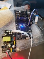
Show a photo of your board, please.
The last picture shows that the connection is ...
Are you connecting directly to USB?
Show a photo of your board, please.
The last picture shows that the connection is ...
Are you connecting directly to USB?
File paths must contain ONLY English letters. And as short as possible.

I was meaning modifying the windows image, because some of the things I gut have an effect on running programs sometimes. Not ISO for unzip. I use 7-zip. Used to use winrar, but no longer.Why ISO??? There WinRAR 🙂
I unpacked RAR.
https://drive.google.com/drive/folders/16UA7Rnb4S14PcELDl_GSBLcaL3qzFL3X?usp=sharing
Good point, Does folder structure look like this for you?File paths must contain ONLY English letters. And as short as possible.
I read somewhere that 28nm is the cheapest and most reliable now (low % of damaged chips).. well maybe lower lithography is cheaper if you got own fab🙂 Maybe they didnt consider this.
That solved it! Genius!File paths must contain ONLY English letters. And as short as possible.
Possibly. I bought 4 of these to put one per speaker. So I have the new version with the 3.5mm plugs, the reworked SPDIF plug, etc. I am literally putting one of these in each of four tower 3-way speakers in a custom plate amp!Something is lost in translation... 🙄 🙁🙂
Attachments

If you like that, I have 4x cheap TPA3255 amps (the $25 version), 4x 3EAudio TPA3255 amps, 4x Arylic Up2Stream Pro v3, 4x 800W continuous power supplies, 4x the power supplies for these DSPs, 4x power supplies for Arylic, 4x 12"x12" aluminum sheets to cut and mount the components to, 4x 10"x5"x2.5" heatsinks to bolt to the plates, 4x Scanspeak 30W-4558T00 Subs, 4x SEAS U18RNX/P (I will likely swap these for Scanspeak 18W/4344G00), and 4x SEAS 27TAC/GB tweeters.😳 😳 😳 😳 I envy white envy 🙂
I also have 3 JAB5s (I blew up one playing with it, flipped the wrong switch in sigmastudio, gave up the smoke; I might try to repair at some point, but the pads under the amplifier chip was damaged and I have never repaired pads on a board). Those will likely go into bookshelves or into something I give my nieces and nephews.
Isn't it easier then to buy a DBX DriveRack PA2? 🙂
Or do you want to make something with your own hands?... 🙂
Or do you want to make something with your own hands?... 🙂
Easier, yes, but I started with audio because no GPUs were available to buy. And overclocking CPUs and GPUs is my hobby. I like to build things with my own hands. Also, the DriveRack there has limited EQ potential. What I have designed in sigmastudio is more complex.Isn't it easier then to buy a DBX DriveRack PA2? 🙂
Or do you want to make something with your own hands?... 🙂
So, you have the signal come in, then auto select based on priority which signal to use, then you have the noise gate to filter out noise to that point below that of the track. You also have a bias that exits port 3 out and comes back in through input 3, which then is used with a sample post noise gating delayed roughly the number of samples for the round trip, which is then subtracted from the sample that came back in, which should give a noise sample roughly of the DAC and ADC. I then add the inverse of that noise back into the overall sample, hoping to cancel some noise that otherwise might make it through (although not perfect because at that point, the noise is different from when the sample is taken, but should be able to help to a degree). Then you have the time alignment and sensitivity matching for each driver, the infrasonic filter for the sub, the PEQ for overall and for each driver, then the FIR correction for each driver and overall to help with phase issues with the crossover points. Then another delay in signal to align both paired loudspeakers together.
You cannot do all that with the device you posted. And this is per speaker! lol
- Home
- Source & Line
- Digital Line Level
- Cheap ADSP21489 + 4in / 6out PCM1798 board