If you don’t have genuine IRF610’s it is possible that they can fry out and die shorted out, which is why the voltage went up. 3-4v drop is normal for a mosfet cap Mx.
Another trick is use a 19v laptop supply and skip the cap Mx. Just use a CLC filter. 470uF and 1mH 470uF with 50ohm in parallel with the 1mH.
Another trick is use a 19v laptop supply and skip the cap Mx. Just use a CLC filter. 470uF and 1mH 470uF with 50ohm in parallel with the 1mH.
Okay, thanks for the alternative, X! Yeah, not sure what happened, but I purchased them from Mouser not too long ago. I'll eventually get everything running, but I may go with that alternate idea.
If you got them from Mouser they are real. Sometimes you can fry them with static discharge. Discharge your hands or wear anti static wrist straps before touching them. It is winter and dry air and wool or fleece sweaters make lots of static.
An ohm meter between any two pins of a MOSFET should measure more than 10kohms. Single digit ohms means it is fried and short circuited.
An ohm meter between any two pins of a MOSFET should measure more than 10kohms. Single digit ohms means it is fried and short circuited.
These are some nice examples:
Simple follower from Nelson Pass
4W SE Class-A by Lineup
Jumas preamp with BF862
Trying to find the best amp for a compression driver.
Lineups circuit can be lower in gain with really good THD values but well, it already has 7 transistors.
The follower could be used straight.
If you need some gain you can combine 1&3.
Similar to here: MOSFET Source Follower Headamp (XRK971)
Jumas pre can be changed to a circuit with just 2 FETs or a even simple single stage/FET amplifier/buffer.
This has only 6 actives. De-rate the PSU to +/-15v and probably a good range for a sensitive CD.

but overall, exceeds the dozen components count.
The LuFo Lite might work well for you as CD amp.
but overall, exceeds the dozen components count.
The LuFo Lite might work well for you as CD amp.
Thanks xrk971. I tried lineups amp which rellay is a beautiful thing that measures well. The Pass follower is built on perfboard and will be tried soon.This has only 6 actives. De-rate the PSU to +/-15v and probably a good range for a sensitive CD.
View attachment 1016745
but overall, exceeds the dozen components count.
The LuFo Lite might work well for you as CD amp.
Made layout for the pass follower plus jfet preamp. Not yet sure if I need that but will post Gerber's for anyone to try when I'm finished
Thanks, X. Yeah, I wear a grounded wrist strap and I placed the gate resistor first on my pcb before the mosfet. I'll check for a short but my best guess is that I had a brain fart and forgot my wrist strap at some point. Also, I had the brick plugged in first, then plugged it into the DC jack while it was hot, so not sure if the 'instant on' killed the mosfet. I should probably plug in the DC side first, then the AC side. 🤷♂️
The BF862/IRF610 is simple, but proving a little tricky to get working. The cap multiplier did have a fried IRF610. A replacement got that working just fine and I had one channel that is working to spec. The voltages measured are really close to the sim with the cap multiplier providing 19.8V.
However, I've built 2 additional channels that are proving to be a puzzle. On both, the voltage measured at the IRF610 source pin is around 9.8 volts. The voltage at the drain pin of the BF862 is 14V, and around 1.2 V at the gate of the jfet. I'm thinking the jfets aren't working to spec on these 2 boards like it is on the first board. I should take a closer look at these jfets to make sure they are within spec. X, does that sound like a reasonable approach? This is my first trip in working with discretes. I'm used to plugging in opamps most of the time.
However, I've built 2 additional channels that are proving to be a puzzle. On both, the voltage measured at the IRF610 source pin is around 9.8 volts. The voltage at the drain pin of the BF862 is 14V, and around 1.2 V at the gate of the jfet. I'm thinking the jfets aren't working to spec on these 2 boards like it is on the first board. I should take a closer look at these jfets to make sure they are within spec. X, does that sound like a reasonable approach? This is my first trip in working with discretes. I'm used to plugging in opamps most of the time.
Update: the two boards with higher voltage measurements appear to be genuine bf862s. The board that measures corectly has a jfet I don't recognize. Not sure what it is but I am tracking it down
What’s the code on the unknown one? I wonder if you have the resistors set for 2SK209GR but using BF862?
Okay, here's some more data to crunch on -
- I found that the unknown jfet is an OnSemi CPH3910 as I found the datasheet indicated the markings. I purchased some of these from Mouser a few years back after reading about it in a thread discussing BF862 alternates. At the time, I noted that it seemed similar in specs to the BF862, so I picked up a few to try out. Somehow, this chip got mixed in with my BF862s.
- I had purchased some BF862s from Mouser and a buddy of mine gave me his because he lost interest in doing anything with them. He didn't remember the source, but was really positive that they weren't fakes. The markings appear exactly the same with 2aw written on them and vertical date codes imprinted to the rate. His chips he gifted me indicate a 90 code and mine have a 25. The two pcbs not measuring within your spec had a 90 date code, so I've switched one pcb out with a 25 date code chip and the results are nearly identical.
- Resistor values: 1k1 (tied to positive rail) and 47 ohms (to IRF610 gate) connected to the drain of the BF862. Source has a 68 ohm in series with a 250 ohm resistor that is then tied to ground. There is a 22k resistor connected to the gate and which is then connected at the 68 ohm/250 ohm node junction.
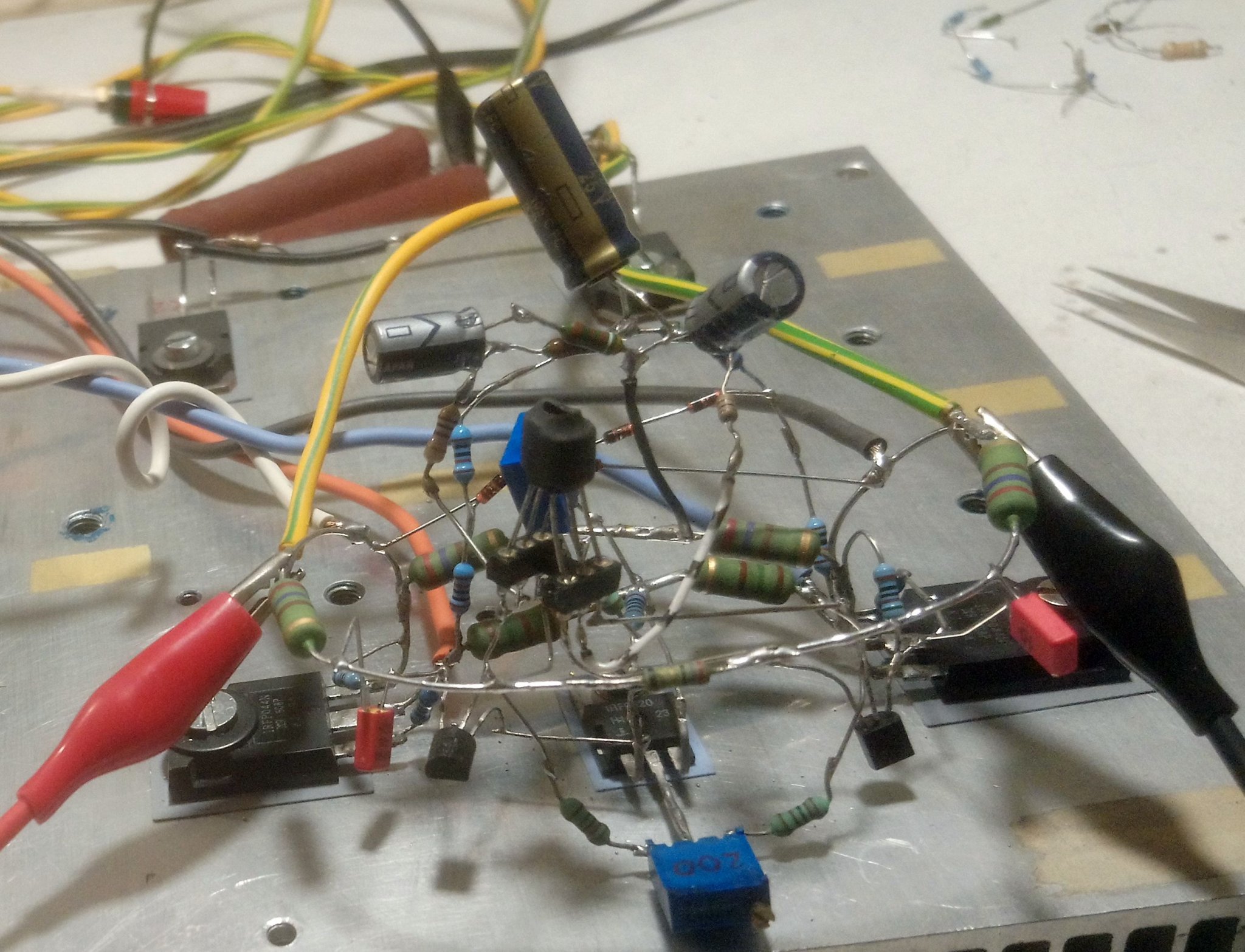
Please take a few closeup photos from different angles so that I can see what the PCB looks like or is this a P2P board? It’s a very simple circuit and if you are getting strange results it’s usually a cold solder joint or a part is way off. It might help if you posted questions in the actual thread. We can look at the schematics.
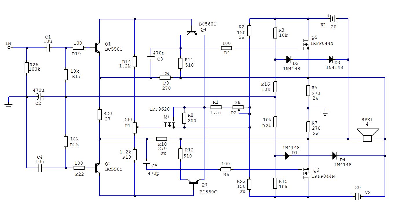
Just to confirm, this is the amp we are talking about right?

Check for a cold solder joint at R111 and R112 above. If no current flows, you won’t get the correct gate bias voltage at the MOSFET. The gate should be about 5v below drain. So for 20v drain, around 15v.
Just to confirm, this is the amp we are talking about right?
Check for a cold solder joint at R111 and R112 above. If no current flows, you won’t get the correct gate bias voltage at the MOSFET. The gate should be about 5v below drain. So for 20v drain, around 15v.
Last edited:
I think I may have just found another candidate for a Fistful of Solder amp. This one is by Juma and Joe Berry and it’s a Circlotron!
https://www.diyaudio.com/community/threads/joe-berrys-circlotron.384070/post-6980819
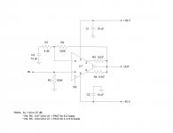
This is Juma’s deadbug amp:
https://www.diyaudio.com/community/threads/joe-berrys-circlotron.384070/post-6980819
This is Juma’s deadbug amp:

It fits in a fist so technically qualifies. You will still need all the ancillary parts that go with the chip amp.
OK, here's one based on the Apex Microtechnology PA12 power op-amp. Nine components including the PA12 chip, eleven if you count the socket and pcb. Nothing special in the design, just a basic op-amp circuit, pure and simple. The board measures 30 mm x 50 mm. This puts out 75 wrms into 8 ohms and 125 wrms into 4 ohms, per channel. I put 8 together in one 2 RU chassis with 2 power supplies for a dual 4 channel amp to run an active x-over system. Sounds good.
Attachments
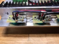
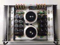
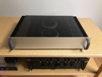

Very neat and simple. More components in the psu section than the amps almost. Looks like there is enough capacitance to power a nuclear submarine.
Perhaps. Doing my best to keep our fleet in service, one uF at a time. Thanks again.Looks like there is enough capacitance to power a nuclear submarine.