If you tallk about the resistor, it is to be sure too kill all the transcient of the 7xxx reg, lol ! Yes put nothing at the output of this ic reg and just decouple the feets of the opa load, 10 to 100 uF there plus itd closer 0.1 on the opa pins to sleep better (and have tigther low end) will be enough, and keep the transcient of the the 7xxx regs, no ? And put 0.1 uF rigth at the output of that reg to be sure it oscillates (I think i even prefer the RC) !Surely, at some point the technical reality of the LF cut-off frequency and the effect component values has on it has to kick in somewhere along the line or do you think a value that gives a 100Hz cut off can somehow overcome that limitation by its exotic nature?
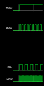
Hi jpk73 🙂Zoran, did you check my simulation I posted in #3957? Attached a screenshot of the output of my circuit (in this case fed from the PMD200): as far as I understand the timing satisfies your remarks - or am I missing something?
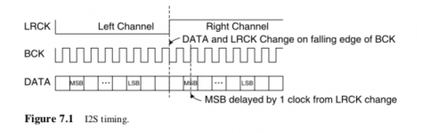
I just spot that You invert BCK signal at the input as I2S line?
Take a look at the standard BCK is changing state from 1 to 0 within LR latch changing the states.
So i think that BCK should be inverted in the source stimulus?
Try change the BCK generator it to strat the opposite value from present?
Attachments
Hi jpk73 🙂
I just spot that You invert BCK signal at the input as I2S line?
Take a look at the standard BCK is changing state from 1 to 0 within LR latch changing the states.
So i think that BCK should be inverted in the source stimulus?
Try change the BCK generator it to strat the opposite value from present?
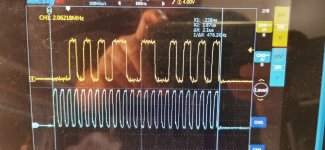
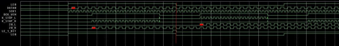
Inverting BCK is only for simulation, not in the actual circuit. Output format of PMD200 is not i2s, see attached scope shots:
Attachments

It is about any component in general and the statement "experimenting and listening are what matters."If you tallk about the resistor, it is to be sure too kill all the transcient of the 7xxx reg, lol ! Yes put nothing at the output of this ic reg and just decouple the feets of the opa load, 10 to 100 uF there plus itd closer 0.1 on the opa pins to sleep better (and have tigther low end) will be enough, and keep the transcient of the the 7xxx regs, no ? And put 0.1 uF rigth at the output of that reg to be sure it oscillates (I think i even prefer the RC) !
Maybe the 1R plus the serie 10 000 uF was a little provocative with its 16 hz cut off I have to admit.
All. I use FC for analog sides; imho silmic 2 and FR are ok for the digital 5V and FC too.
But anyway on Ali your parts will have a chance to be fake. Whatever you do, source for genuine parts. Silmic 2 have a lot of imitations. FM ask care and tests. Remember to look the size for vias gap and diameter on datasheets. Miro did a bom.
But anyway on Ali your parts will have a chance to be fake. Whatever you do, source for genuine parts. Silmic 2 have a lot of imitations. FM ask care and tests. Remember to look the size for vias gap and diameter on datasheets. Miro did a bom.

LT1963EQ#PBF is unobtanium part now....>>Why this choice LT1963 and LT3015 ?
This PDF led me to those components A comparative overview of power supply regulator designs with listening tests - PDF Free Download
and also because of the still unsurpassed popularity of THT
But I barely managed to find it from the USA. 😛
Aaa 🙁 sorry. You used PMD200 output format. But isn't the PMD200 alredy compatible? PMD100 is.Inverting BCK is only for simulation, not in the actual circuit. Output format of PMD200 is not i2s, see attached scope shots:
I know from the other topic that You finished controller for the PMD. Was it 100 or 200 type?
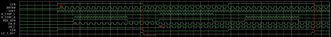
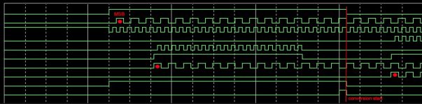
There is one solution for not to going into conversion in the same time digital word is loaded. LE could be used as it is or just one pulse.
Stopped clock. For 16 18 20 and 24 bit words.
(WIndow where words and clock are happening, is not exactly in the middle. For instance for 16 bits (32-16)/2=8 8 bits before word and clock and 8 bits after LSB. The same blanc period of time between going to conversion LE event. For other word length (32-18)/2=7, (32-20)/2=6, (32-24)/2=4.
.
I will do it in next version maybe in with inverting data in the time window and recklocking with MCK)
Attachments
Last edited:
I see. I can buy caps from local vendors and also in distribution. I don't buy on ali. Now I got a many opinions and all of them say "buy and use" Silmic 2. They are better for sound. I also found the video with test of the different caps (YouTube) with more useful info. I haven't decided yet - still looking.All. I use FC for analog sides; imho silmic 2 and FR are ok for the digital 5V and FC too.
But anyway on Ali your parts will have a chance to be fake. Whatever you do, source for genuine parts. Silmic 2 have a lot of imitations. FM ask care and tests. Remember to look the size for vias gap and diameter on datasheets. Miro did a bom.
That is what I say to experiment yourself with your hifi system.
There is the bom by Miro you should follow if you do not know what you are doing (for illustration somz negative rail reg ic do need output cap and so on). If you read the thread some advices have been shared about BOM and members likings as dor the opas.
Noone but you can say what sounds best in your system.
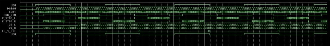
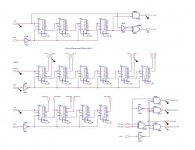
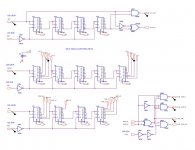
I made corrections to the format. Main idea is that all clocks and datas are happening in the "window" that is symmetrical to the Latch Enable events. So same number of blanc SCT time is prior and after the reception of DATA word. Also I made correction about position of SCKs and DATA. Now it is like in data-sheets. Time delay is much lower than in Right Justified composition. So one shift register for data delay went out.
.
(in earlier post BCK is moved half of BCK to the MSB. I spot this too late to edit post before. 🙁 )
Now everything is as standard. 🙂 please see the timing line of AD1862 and compare.
.
Window is not fixed and could be used for 16, 18, 20 and 24 bit word depending of DAC chip. For Analog Devices and TI Burr Brown DACs
.
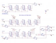
This is results for AD1862. I will try 74F series DIP because of same level of technology and dimensions as DAC chip. Also 74AHC could be used.
.
In the SCH are some additional signals that I use as sort of reference that is no needed for DAC operation and could be omitted...
.
(in earlier post BCK is moved half of BCK to the MSB. I spot this too late to edit post before. 🙁 )
Now everything is as standard. 🙂 please see the timing line of AD1862 and compare.
.
Window is not fixed and could be used for 16, 18, 20 and 24 bit word depending of DAC chip. For Analog Devices and TI Burr Brown DACs
.
This is results for AD1862. I will try 74F series DIP because of same level of technology and dimensions as DAC chip. Also 74AHC could be used.
.
In the SCH are some additional signals that I use as sort of reference that is no needed for DAC operation and could be omitted...
Attachments


Last edited:
Yes but maybe for some other SMD package DAC? (For instance like SMD PCM1794). These DACs are in Bigger DIP-s and I think that is maybe more appropriate to use the same size other logic?
This F series are very fast... 😎 please take a look at the specs. And I have it around in local store - still. They are far more expensive than classic HC series but it is not a big issue. AC series are also very fast and good. I dont have nervs to order from outside...
They don't have in the store inverters F04. 🙂 or F00 to made an inverter, but they have F02 I think I can make inverter with...
Yes AHCT could be also OK?
Also DIP packages has bigger DIE and more "room" between the internal elements? That could decrease noise and other unwanted things in audio domain... Somehow I like it more additionally because we simply can pull out and replace IC?
.
"By 1986 surface mounted components accounted for 10% of the market at most, but was rapidly gaining popularity.[2] By the late 1990s, the great majority of high-tech electronic printed circuit assemblies were dominated by surface mount devices." From the WikiP, I didn't knew that it was like this...
The Japanese have this order and method in Yamaha devices with PCM63-PI see. I can buy caps from local vendors and also in distribution. I don't buy on ali. Now I got a many opinions and all of them say "buy and use" Silmic 2. They are better for sound. I also found the video with test of the different caps (YouTube) with more useful info. I haven't decided yet - still looking.
On the signal path / Coupling: Nichicon Muse ES, Elna Silmic, Elna Cerafine, Elna Tonerex, Muse FG
Power supplies (Analog): Elna Tonerex, Nichicon Muse KZ, Panasonic FM or Nichicon UHE, Elna Silmic / Cerafine, Muse FG
Power supplies (Digital): Sanyo OS-Con, Panasonic FM, Nichicon Muse KZ
There is no end to this madness ... There is always something extra, some new expense 🤣
Also DIP packages has bigger DIE and more "room" between the internal elements? That could decrease noise and other unwanted things in audio domain... Somehow I like it more additionally because we simply can pull out and replace IC?
A DIP package is unlikely to have a different die from the SMD equivalent. But DIP has a larger leadframe hence more inductance. The extra inductance gives more 'bounce' on the supply rails from switching and hence more noise on the outputs.
- Home
- Source & Line
- Digital Line Level
- DAC AD1862: Almost THT, I2S input, NOS, R-2R