
The big bad mouse blocked that content here in the US, lol
I've got a pair of Edcor 1:2 WSM series line-matching trafos with center-taps on the secondary I could try in autoformer mode I suppose. Other than a B1 buffer, I don't have a simple buffer circuit to put in front of it.so, either put buffer+autoformer in front (getting M2 derivative, later DEFiSIT) or any decent active gain stage


Ok I'm back at my computer 🙂 Edcor doesn't seem to have a handy pdf spec sheet for these but this is the model series. I have the 600R to 2kR4 half watt rated ones (WSM600/2.4K).
Thank you ZM.
Thank you ZM.
Attachments
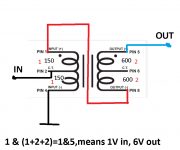
Wow, thank you. Autoformers remain mysterious to me (I'm not very smart).here it is
black impedance ratios
red voltage ratios
final 'ritmetic written at bottom
B1 ( without protection series resistor in output) will drive 150R nominally, what we know from various Papa's gadgets
So I'll take the B1 output directly off the output capacitor then, or do I need to break the connection to the 1k/221k voltage divider as well? (Edit: I don't think I need to break it but that means the autoformer / SIT amp is now in parallel with 222k of resistance to ground. I don't know what the reflected input impedance of the SIT amp is but I suspect it's quite low?)
Last edited:
Same procedure for whitenecks?
if not, I best get some sun before embarking on a SIT project
well, even if ya silly Vikingsess got your horns whooped last time when you messed with us Indians ( that before Columbo), we Indians are going to help ya silly Vikings
just try to explain yourself more clearly .......

Well, I got impatient, and built it anyway without modifying my B1 buffer. Long story shortened, these Edcor trafos don't play nice in my hands with the unadulterated output of my B1 buffer. I kinda knew this already as I'd originally bought these trafos as a potential output mod for the B1, tried them in their own separate little box with RCA interconnects between first, and didn't like the sound at all. So it's no surprise to me that they didn't sound very nice directly connected to the B1 upstream of this Redneck SIT.
(Also there was an awful lot of mains hum when I attempted to use the B1 powered by it's own wall wart in this configuration. It wasn't until I powered it off of the same bench supply as the ZM Redneck SIT that the hum went away (positive rail only, but common ground- lots of common grounding actually). But still, I didn't quite like the B1 sound here, too smooth and muted for my taste.)
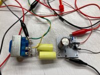
What worked for me is a direct connection- no buffering after my bluetooth input, just input hard wired into the trafo primary as shown in ZM's diagram and the first picture below. I left the 10uF coupling caps in and they sounded better than when I jumpered across them. The sound is neat to me- brassy and resonant, a recognizable trafo sound, and has more volume and thrust now than when the input was just into the coupling caps. Vaporwave and synth music actually sounds smoothed out and good, which I thank the little trafo for. I'm seriously tempted to build this as an integrated amp, with it's own volume pot, only I'm not sure where to put it (probably on the secondary?), or what value to use. I have a couple blue ALPS pots around that could work.
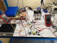
The actives got scorching hot again though, and that's a concern. I have yet to put a current sense resistor in so I have no idea how much current this thing is drawing, or if it can be dialed down to something reasonable in the final amp without impacting the sound.
(Also there was an awful lot of mains hum when I attempted to use the B1 powered by it's own wall wart in this configuration. It wasn't until I powered it off of the same bench supply as the ZM Redneck SIT that the hum went away (positive rail only, but common ground- lots of common grounding actually). But still, I didn't quite like the B1 sound here, too smooth and muted for my taste.)
What worked for me is a direct connection- no buffering after my bluetooth input, just input hard wired into the trafo primary as shown in ZM's diagram and the first picture below. I left the 10uF coupling caps in and they sounded better than when I jumpered across them. The sound is neat to me- brassy and resonant, a recognizable trafo sound, and has more volume and thrust now than when the input was just into the coupling caps. Vaporwave and synth music actually sounds smoothed out and good, which I thank the little trafo for. I'm seriously tempted to build this as an integrated amp, with it's own volume pot, only I'm not sure where to put it (probably on the secondary?), or what value to use. I have a couple blue ALPS pots around that could work.
The actives got scorching hot again though, and that's a concern. I have yet to put a current sense resistor in so I have no idea how much current this thing is drawing, or if it can be dialed down to something reasonable in the final amp without impacting the sound.
Attachments

Sorry. It's this one, the single rail version.
Attachments
Ok, shorting R104/204 made it louder but it still doesn't sound anywhere near as good as direct input to autoformer. I like the bare autoformer without buffer front end for this.short R104/204 (put 0R)
221K are irelevant ( that big value)
try again with B1 to feed autoformer
So why not just put a 50k audio taper pot to ground after the 10uF coupling cap, with the wiper as input to the rest of the biasing circuit? As a high pass RC this pot in combination with the coupling caps should have a roll-off point of 0.32Hz. At 1K I suppose it's rolling off some of the bass at about 16hz. I'm gonna go try this.
Also I put a current sense resistor in, this amp draws 2 amps with the 45V rail-to-rail bias. 90W of dissipation! No wonder it gets hot.
so it seems that your source ( whatever it is) is having lower Rout that your B1 is having
of course, I don't know how your B1 is made....... proper or not
anyway, B1 V.1 is having Rout in range of 1/S of JFet plus value of whatever source resistance of upper JFet
so you can calc it easily
B1 V.2 , is practically having half Rout od V.1
that's (1/S +Rs) of upper JFet in parallel with (1/S +Rs) of lower JFet
anyway, if you found best way to drive your autoformer, stick with it
regarding
you don't wanna mess with anything which will introduce ground in biasing circuit I posted
and - think twice - what's Rout of Volume Pot
you need low Rout to drive that circuit properly; not so low as needed for driving autoformer, but still
of course, I don't know how your B1 is made....... proper or not
anyway, B1 V.1 is having Rout in range of 1/S of JFet plus value of whatever source resistance of upper JFet
so you can calc it easily
B1 V.2 , is practically having half Rout od V.1
that's (1/S +Rs) of upper JFet in parallel with (1/S +Rs) of lower JFet
anyway, if you found best way to drive your autoformer, stick with it
regarding
So why not just put a 50k audio taper pot to ground after the 10uF coupling cap,
you don't wanna mess with anything which will introduce ground in biasing circuit I posted
and - think twice - what's Rout of Volume Pot
you need low Rout to drive that circuit properly; not so low as needed for driving autoformer, but still
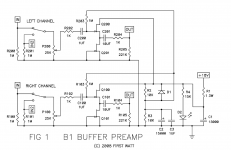
This B1 is built from a PASS Labs board and JFET package and should have an Rout of about 50R if I'm reading the pdf correctly.
I messed around with an audio taper pot as described and yes ZM it did horrible things to the DC offset. I could see the speaker cone thrust all the way out and sucked all the way in depending on whether the pot was connected to ground or negative rail. Tying the wiper to the opposite end of the pot had no effect; the pot itself couldn't drop the volume to zero in that configuration.
I messed around with an audio taper pot as described and yes ZM it did horrible things to the DC offset. I could see the speaker cone thrust all the way out and sucked all the way in depending on whether the pot was connected to ground or negative rail. Tying the wiper to the opposite end of the pot had no effect; the pot itself couldn't drop the volume to zero in that configuration.
- Home
- Amplifiers
- Pass Labs
- Redneck ZM DEFiSIT/DEF biasing