Like this one on fig. b? What is the benefit? Thanks in advance.The world needs a low cost source of progressive wound toroid OTs.
Working on couple different Hybrid amps , there`s my first very simple oneOnly takes a few resisters to fix transformer distortion. (Patent US4614914 ) The problem with transformers (good ones) is cost and weight. But I'll take them over OTL. Mosfet followers are fine too. The world needs a low cost source of progressive wound toroid OTs.
Singleton CFA amp, it is DC coupled and consist from one small triode at input , one BJT as VAS ,and known couple of Hitachi power latfets as OPS , it is around 50W /16 ohm AB class with around 10W out working in pure A class , simulation says , it is very stable with very wide bandwidth , THD= 0,007% @ 1W , perfect square wave @ 20Khz , SNR 113dB/1Khz ,excellent PSRR ,and with THD spectra similar to some SE amp,and there`s no any output transformer.
Attachments

Last edited:
Similar to fig. B. The scheme uses "chevron" shaped winding motions. The idea is to keep turns with similar voltage together so as to minimize distributed capacitance and to do that in a uniform way (no gaps or notches) so as to avoid any local flux loops that would cause leakage inductance. Since there are toroid winding machines that will do this automatically, it is logical to use them for OTs. But they are more expensive (require accurate control of toroid angular position and digital control) than the simpler "random" wind machines.Like this one on fig. b? What is the benefit?
Power toroids are actually wound in the "random" way to maximize distributed capacitance so as to improve the power factor (cancel some of the inductance), completely opposite to what you want for an OT.
------------------------------------------------------------------------
If only Mosfets could come in glass bottles and glow.
I would like to find a scheme where a Mosfet could be used to enhance a small OT, so as to extend the low freq. capability. And there are schemes to do this, but too complicated or they use a complete SS amplifier add on. I suppose a power IC amp booster would come close.
Last edited:

Thanks smoking-amp! If I understand correctly, with a similarity with triode capacitance, having turns with similar voltage close to each other will minimize the "Miller" effect: you still have a capacitance, but being the two "faces" of the capacitor at similar voltage, the effect is minimized.
Yes. Also important to avoid any notches or gaps in the wind to minimize leakage inductance.
It is also important that each half of a conventional center tapped primary cover the whole toroid (with good insulation between them) so as avoid big time leakage inductance. A progressive single layer Circlotron wind (1/2 the turns) would solve that well. Some comments I've seen favor doing interleaved partial primary and secondary winding layers, but it seems to me that just doubles distr. C and maybe reduces leakage L a little. It certainly would increase the cost.
It is also important that each half of a conventional center tapped primary cover the whole toroid (with good insulation between them) so as avoid big time leakage inductance. A progressive single layer Circlotron wind (1/2 the turns) would solve that well. Some comments I've seen favor doing interleaved partial primary and secondary winding layers, but it seems to me that just doubles distr. C and maybe reduces leakage L a little. It certainly would increase the cost.
Last edited:
But this is an amplifier with global NFB...Working on couple different Hybrid amps , there`s my first very simple oneSingletonCFA amp, it is DC coupled and consist from one small triode at input , one BJT as VAS ,and known couple of Hitachi power latfets as OPS , it is around 50W /16 ohm AB class with around 10W out working in pure A class , simulation says , it is very stable with very wide bandwidth , THD= 0,007% @ 1W , perfect square wave @ 20Khz , SNR 113dB/1Khz ,excellent PSRR ,and with THD spectra similar to some SE amp,
and there`s no any output transformer.
Or, in another perspective, it is just winding sectioning. I think sectioned winding with "wild" section patterning will have even less capacitance than B. Something like this.Similar to fig. B. The scheme uses "chevron" shaped winding motions. The idea is to keep turns with similar voltage together so as to minimize distributed capacitance and to do that in a uniform way (no gaps or notches) so as to avoid any local flux loops that would cause leakage inductance. Since there are toroid winding machines that will do this automatically, it is logical to use them for OTs. But they are more expensive (require accurate control of toroid angular position and digital control) than the simpler "random" wind machines.
Power toroids are actually wound in the "random" way to maximize distributed capacitance so as to improve the power factor (cancel some of the inductance), completely opposite to what you want for an OT.
------------------------------------------------------------------------
If only Mosfets could come in glass bottles and glow.
I would like to find a scheme where a Mosfet could be used to enhance a small OT, so as to extend the low freq. capability. And there are schemes to do this, but too complicated or they use a complete SS amplifier add on. I suppose a power IC amp booster would come close.
I like the idea of Crazy Drive, but it requires driver stage with a lot of swing and low output impedance. Practically difficult if one wants a tube-only design.With a no Fdbk pentode you get an output impedance (Rp) that varies as 1/Sqrt(current) and a forward gm that varies as 3/2 to 2 power law.
Class A P-P could clear some of that up. Another alternative would be Crazy Drive, pic below. Constant gm but still 1/Sqrt(I) Rp.
A 6V6 would get you 70K to 80K Ohm Rp. Could also use a cascode circuit to get high Rp, could be used with Crazy Drive too ( bottom tube ) for constant gm as well.
View attachment 1062337
By contrast, the ease of driving a pentode output stage is so appealing. A 12AX7 section driving a PP pair of output pentodes to 120 W...
To the choice of driver in post#19
At the first glance, drivers with beefier motors are preferable: stronger magnets, higher gap flux, more sensitivity. But what appears on surface may not stand true on closer look.
The driver #3 (Jensen Concert) has thick iron yoke because it uses underhung VC. Of the three, it has the largest gap cross-section. Because there is a limit on how much heat a field coil can dissipate, this driver in fact has the lowest gap flux density of the three.
Drivers ## 2 and 3 are rated 20 W, whereas driver #1 is 5 W. Higher power necessitates thicker VC wire, which in turn requires wider gap. So, bigger motors of high power drivers do not necessarily translate into higher flux density.
Power capacity comes with the increased VC mass, and thus increased mms. Driver's mechanical damping has two components: losses in cone/surround/spider materials and air friction, both invariant for a given type and diameter of cone. A cone with higher mass (bigger VC) will have higher Qms, everything else equal.
So, it seems like the overall winner is #1.
Last edited:
sser2
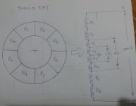
IMO the simplest & best way to use toroid OPT for GNFB-free amp with power pentodes is to use Circlotron based OPS ,
but for best results that OPT have to be connected as symetrical autoformer with center tap earthed ,
for example if you use 8 x PL36 (EL36) you can get around 120W out. , in that case total OPT impedance can be around of only 200 ohm , I think such toroid OPT can be done manually (DIY) very easy ,
Philips AG9007 OTL Circlotron amp can be very good starting& reference point for you , just ignore complete front end section altogether with those two independent GNFB loops ,on that Philips amp I like very elegant PSU where is aranged that EL36 plates work with +300V and screen grids with only 150V , that ensure to EL36` relative long lives ,and all that operating in pure pentode mode ,
here`s my idea how you can try to wind such simple autoformer OPT , at least that will be way if I DIY such toroid output power autoformer for me , there`s no layers of wires , if possible every section is made just wire by wire side by side ,in the same way as you show in post #47, but on the end I must point that I`m not very big expert for OPT`s !
Attachments
Thanks! A very interesting OTL with no nfb (if one doesn't count the speaker autoformer). Perhaps will benefit from lower Rp pentodes such as 6Y6 or 25L6, and adding more output tubes in parallel. A drawback, though, is a need for high value output capacitor.sser2
IMO the simplest & best way to use toroid OPT for GNFB-free amp with power pentodes is to use Circlotron based OPS ,
but for best results that OPT have to be connected as symetrical autoformer with center tap earthed ,
for example if you use 8 x PL36 (EL36) you can get around 120W out. , in that case total OPT impedance can be around of only 200 ohm , I think such toroid OPT can be done manually (DIY) very easy ,
Philips AG9007 OTL Circlotron amp can be very good starting& reference point for you , just ignore complete front end section altogether with those two independent GNFB loops ,on that Philips amp I like very elegant PSU where is aranged that EL36 plates work with +300V and screen grids with only 150V , that ensure to EL36` relative long lives ,and all that operating in pure pentode mode ,
here`s my idea how you can try to wind such simple autoformer OPT , at least that will be way if I DIY such toroid output power autoformer for me , there`s no layers of wires , if possible every section is made just wire by wire side by side ,in the same way as you show in post #47, but on the end I must point that I`m not very big expert for OPT`s !
No need for any output capacitor if you design OPS DC offset & bias network in proper way , and not in that extremely simple way as is in that Philips amp.
Low mms, the holy grail of mechanical damping
Considering electrostats, the speakers with least distortion and perfect damping, it can be deduced that improving conventional speaker can be achieved by reducing its moving mass. VC wound with aluminum wire. Removing everything that is not necessary, such a whizzer cones or dust caps.
For boxed speakers relying on electric damping, mms doesn't seem to be that important, as it can be compensated by increasing BL. But I believe that this approach, compensating one brute force with another, is fraught with increased distortion.
Speakers could be high mms and high sensitivity at the same time. I once tried Electrovoice DL12, a 12" pro driver, 100 dB, mms=33 g, BL=20 Tm. It didn't sound good. Claimed harmonic distortion was 3% at 10% rated power.
VC shorting rings
Bulky copper rings in close proximity to VC have been used as electric damping method not dependent on low output impedance of driving amplifier. But there were opinions that they cause overdamping, decreased efficiency, and dull sound. I have no experience of my own, this information is what I found researching the matter. The mechanism should apply to regular speakers because iron pole pieces are conductive, albeit less than copper.
Bulky copper rings in close proximity to VC have been used as electric damping method not dependent on low output impedance of driving amplifier. But there were opinions that they cause overdamping, decreased efficiency, and dull sound. I have no experience of my own, this information is what I found researching the matter. The mechanism should apply to regular speakers because iron pole pieces are conductive, albeit less than copper.
Overdamping? COpper caps work to reduce inductance which is what causes a rise in impedance as frequency goes up.
dave
dave
I still havent heard a word on this field coil's average current increasing when the amplifier is played loudly, if it's arranged as part of the B+ circuit. What does that do to the speaker characteristics? Why do people even like field coil speakers in this day anyway, unless something's happening that a fixed magnet driver cannot do?Because there is a limit on how much heat a field coil can dissipate,
They do indeed reduce le, but at the expense of siphoning off the motive AC magnetic field of VC and dissipating it as Eddy current heat. Like a shorted turn in a transformer. They also act as Faraday rings - generating magnetic field that opposes the movement of VC.Overdamping? COpper caps work to reduce inductance which is what causes a rise in impedance as frequency goes up.
dave
Electromagnet magnetization follows the standard B-H curve. Close to or beyond magnetic saturation, more or less magnetizing force does not change magnetic flux. So, a properly designed series field coil is close to saturation at its minimal current, extra current does not change magnetic field.I still havent heard a word on this field coil's average current increasing when the amplifier is played loudly, if it's arranged as part of the B+ circuit. What does that do to the speaker characteristics? Why do people even like field coil speakers in this day anyway, unless something's happening that a fixed magnet driver cannot do?
One reason I am using FC drivers is that I cannot find anything permanent magnet with same characteristics. There were similar drivers with Alnico, but Alnico magnets are weak and they tend to lose strength with time.
You are absolutely right: speakers with permanent magnets do exactly same things as those with FC. They play music. But that said, in my experience, which is of course personal and highly subjective, FC sounds better than Alnico, and Alnico better than ferrite. For me it is worth the trouble of making FC power supplies.
Really? They just design the fun out of everything, dont they.So, a properly designed series field coil is close to saturation at its minimal current, extra current does not change magnetic field.
I would think it'd be advantageous to have Qts go down some, with the increase in current - hence magnetization - from the amplifier making more power when played loudly. One would think the designers would have left a little wiggle room for that. But, I could be wrong about it.
- Home
- Amplifiers
- Tubes / Valves
- No-feedback pentode amplifier