Yes, that's what the fun of this hobby is - finding the way to the sound you enjoy the most.TL;DR
After 56 years of favouring UL, GNFB and PP I discovered that when properly done a SE amplifier with CFB puts most tube amplifiers to shame. Better to spend some more money on better speakers. Less maintenance costs. YMMV
Mutual damping in parallel drivers
When identical drivers are connected in parallel, their damping characteristics do not change because they have same resonance peaks. But if drivers have disparate resonances, there will be mutual damping. Parallel connection of two drivers whose resonances are far apart will provide damping factor of about 1. Not spectacular, but significant to make a difference in combination with mechanical damping measures.
This approach has been used in the Belvedere console. The two drivers looked the same (#1 in post 17), but their resonances were at 60 and 100 Hz, approximately, due to different suspension stiffness.
As a bonus, the two drivers provide 3 dB bass boost compared to single driver.

To keep it simple, I will recycle an old prototype amp circuit over the coming months. Input and drive will be via 6AH9 compactron configured as an asymmetric mu stage. The triode section is much like half a 6CG7 (mu=20). The pentode section is the 12HL7 (configured as the "triode from hell").
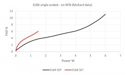
The output device will be a 6CZ5, working into a cheap 5K:8R single-ended transformer. I am expecting an output impedance in the order of 50 Ohms, and 2% to 3% THD at 1W. I may swap in EL84s - the Mullard data shows there will be nothing special for the measuring equipment. 🙂
The speaker will be a Pioneer from the stash mounted in recycled enclosures. Measurements will use REW and other open source software. Will be a fun experiment.
Attachments
Example? Schematic? It'd be nice to see what you mean, if unfortunately one isnt in a position to actually hear it ;')I discovered that when properly done a SE amplifier with CFB
The distortion vs. power graph is interesting - pentode connection having less distortion than triode connection. Defies conventional wisdom.To keep it simple, I will recycle an old prototype amp circuit over the coming months. Input and drive will be via 6AH9 compactron configured as an asymmetric mu stage. The triode section is much like half a 6CG7 (mu=20). The pentode section is the 12HL7 (configured as the "triode from hell").
The output device will be a 6CZ5, working into a cheap 5K:8R single-ended transformer. I am expecting an output impedance in the order of 50 Ohms, and 2% to 3% THD at 1W. I may swap in EL84s - the Mullard data shows there will be nothing special for the measuring equipment. 🙂
The speaker will be a Pioneer from the stash mounted in recycled enclosures. Measurements will use REW and other open source software. Will be a fun experiment.
Flea power is a viable proposition with speakers suitable for current drive. But I am contemplating the opposite approach, high power (>100 W continuous) in order to obtain few really clean watts with enough headroom for any transient scenario.
I'm not too surprised that pentode has less distortion. EL84 doesn't make a terribly linear triode, and you have to bias at a higher voltage and lower current to get a symmetric optimized operating point (unless you are going for A2). With pentode connection, you can set the operating point at a lower voltage and higher current where the pentode curves are more linear.
I still havent heard a word on this field coil's average current increasing when the amplifier is played loudly, if it's arranged as part of the B+ circuit. What does that do to the speaker characteristics?
Big field coils go in parlor radios which were resolutely CLASS A to past lease-breaking output.
Theater field-coils had their own power unit.
Why do people even like field coil speakers in this day anyway,
Why does the Stanley Steamer pass my house every year? And a string of Model As every month? My neighbor drives a 1935 Chevy to the city every weekend. My other computer is from 2009, which is like a century in PC-years.
Well, I was hoping to hear it had something to do with being able to change the speaker characteristics at the turn of a dial - via a field coil current control. I realize that can be done - some - via simply adding a series resistance in line with the VC connection.Why does the Stanley Steamer pass my house every year?
Or even better, to hear it was all thought out by 1939; they knew and wanted the speaker's VC to have more grip when the set was played loudly. Then they figured out permanent magnets and it was just too expensive to design in the feature...
Aperiodic vent
Aperiodic vent is a mechanical damping contraption for a closed-box speaker. It is a rigid but porous panel inserted in box opening. When air flow - generated by cone motion - passes through the pores, air friction provides damping effect. The best known implementation is the Dynaco/Scan Speak A25:
https://i.pinimg.com/originals/6d/90/f1/6d90f19142b886a5abfcac2f546dc8c7.jpg
The aperiodic vent is rectangular thing at the front bottom of the box. Later on Scan Speak was selling round aperiodic vents for DIY speaker builders.
I got familiar with this damping approach from a 1960s article in the Soviet magazine Radio. They called it "Acoustic Resistance Panel", and described a DIY approach. A stretched sheet of fabric is pressed and glued between 2 perforated boards, with perforations aligned.
The beauty of aperiodic vent is that by tweaking its size and porosity, the extent of damping can be finely adjusted. A small disadvantage may be small amount of hiss from air passing through the pores, but that is only audible with ear very close to the speaker.
Anticipating questions why such good thing was not used more widely, I believe it was deemed unnecessary because electric damping was as good as it gets, and, I guess, it was a patented invention.
In my another hobby, I am restoting a 1937 Plymoth 2-door sedan.Big field coils go in parlor radios which were resolutely CLASS A to past lease-breaking output.
Theater field-coils had their own power unit.
Why does the Stanley Steamer pass my house every year? And a string of Model As every month? My neighbor drives a 1935 Chevy to the city every weekend. My other computer is from 2009, which is like a century in PC-years.
I assume this is the same as tuning the damping of any resonant circuit to the classic "overdamped" or "critically damped". No resonance, no "periodic". Might as well have called it a "shock absorber".The beauty of aperiodic vent is that by tweaking its size and porosity, the extent of damping can be finely adjusted.
Is it going to be shaved?I am restoting a 1937 Plymoth 2-door sedan.
No way. As original as could be, with original inline six (custom aluminum head) and 3-speed manual transmission.Is it going to be shaved?
What you suggest would be an ingenious approach to fine-tuning speaker sensitivity. An application could be in matching drivers in a multi-driver speakers. I've never heard of such thing.Well, I was hoping to hear it had something to do with being able to change the speaker characteristics at the turn of a dial - via a field coil current control. I realize that can be done - some - via simply adding a series resistance in line with the VC connection.
Or even better, to hear it was all thought out by 1939; they knew and wanted the speaker's VC to have more grip when the set was played loudly. Then they figured out permanent magnets and it was just too expensive to design in the feature...
The way to find optimal FC current for an unknown driver is to play a tone while increasing FC voltage, and measure SPL. At the point where SPL stops increasing, the iron circuit is close to saturation. Then go a little higher and stop.
https://www.xr793.com/wp-content/uploads/2017/01/1937-Plymouth-Value.pdf1937 Plymoth 2-door sedan
Brother has an unrestored 1941 Plymouth 4-door. It drives good.
In wartime paint? Thanks for the link!https://www.xr793.com/wp-content/uploads/2017/01/1937-Plymouth-Value.pdf
Brother has an unrestored 1941 Plymouth 4-door. It drives good.
Aperiodic vent is a mechanical damping contraption for a closed-box speaker. It is a rigid but porous panel inserted in box opening.
That is one way of doing it, not usually the best solution.
dave
No. (Do I have the wrong year?) Black with plenty chrome. A farmer bought it new, died in the late 1980s. Bro has it since.In wartime paint?


- Home
- Amplifiers
- Tubes / Valves
- No-feedback pentode amplifier