Hi All,
Just wondering, Would be any benefit in using higher value capacitors in an amplifier's driver stage? currently there are 220uF in the circuit, would be any benefit in replacing it with , let's say 1000uF capacitors?
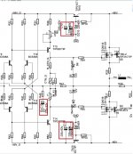
I'm referring to the marked capacitors in the attached schematic.
Thanks
Just wondering, Would be any benefit in using higher value capacitors in an amplifier's driver stage? currently there are 220uF in the circuit, would be any benefit in replacing it with , let's say 1000uF capacitors?
I'm referring to the marked capacitors in the attached schematic.
Thanks
Attachments
Well it depends on the purpose of the cap. In that case as you have a in-series bjt then it’s smoothing so ESR at the frequencies and enough current to drive.
yes adding more capacitance will reduce rail sag IF the ESR and current capability is not being limited.
Adding more capacitance means more inrush which could damage something depending on the schematic.
yes adding more capacitance will reduce rail sag IF the ESR and current capability is not being limited.
Adding more capacitance means more inrush which could damage something depending on the schematic.
Schematic isn’t complete so I might be wrong….
however, the two supply rails feed the hungry output devices at full voltage. As you move to the left,on both rails, there is a voltage regulator transistor using a zener diode to drop the voltage slightly to isolate the input side from any slight ripple cause by big current swings going through the output devices. The caps are on the other side of that voltage regulation so are really only stabilising the low current section. Unless there is still noise or ripples on those rails (left of the regulation) then increasing the capacitor values is probably not going to make an improvement (no harm though).
update: you are correct, that regulation is for the driver devices as well. So perhaps more chance of noise on the rails, which increased capacitance may help. Scope it & see.
the other cap in the middle appears to be the feedback cap (again, a caveat due to the incomplete diagram). If I’m correct, That one is very important & needs to be 100% fit & healthy plus of high quality (extremely stable over frequency & low esr).
Thanks guys.
That's the full schematic for one channel of the amplifier
-----------------------------------------------------

Moderation Edit. Image removed due to copyright concerns being raised.
That's the full schematic for one channel of the amplifier
-----------------------------------------------------
Moderation Edit. Image removed due to copyright concerns being raised.
Last edited by a moderator:
Hi,
Thanks brucem, kindly correct me if I'm wrong but isn't a feedback circuit (C12 & R46) should be connected from output to input? this circuit seems to be connected from input to ground.
Thanks brucem, kindly correct me if I'm wrong but isn't a feedback circuit (C12 & R46) should be connected from output to input? this circuit seems to be connected from input to ground.
Hi,
Thanks brucem, kindly correct me if I'm wrong but isn't a feedback circuit (C12 & R46) should be connected from output to input? this circuit seems to be connected from input to ground.
It looks like R47 and R46 are used to balance the LTP by acting as a potential divider for the feedback. The cap then acts to block DC current. More info: https://sound-au.com/amp_design.htm If you look further down the input into the LTP goes through a RCR filter too - so this would target RF noise/feedback too. The capacitance value for that would be part of the RF filter tuning (athough this structure is R(RC)R.
EDIT: I forgot to say when I've bypassed my cap in my SS amp I noted a DC offset so just be a little careful when playing with the values 😀
Last edited:
The output signal is fed back via the voltage divider which reduces the voltage (most of the voltage is across R47 & the feedback signal is the voltage across R46 + C12).
There is a pretty constant current draw out of the caps and zener-reg/cap-multiplier, so do not think they will affect SQ much. I'd leave as is, they are a sane value. Larger caps may actually give larger loop (layout) and worse performance...
Nope, it's a branded amplifierWhich amplifier is that? DIY?
The manufacturer provided me the schematics only after I promissed him that I will not publish it, I would like to keep my word.Which branded amplifier is that?
???? you have already published it, what are you talking about? You have already broken the promises.The manufacturer provided me the schematics only after I promissed him that I will not publish it, I would like to keep my word.
Sharing the brand of the amplifier would surely be okay? No?

What is the purpose of directly paralleling Mosfets(?) and Bipolar Transistors as output devices?
Never seen this before.
Never seen this before.
My guess is just activating whichever model is to be used, the mos or the bipolar. The simulator I use routinely puts a big red X over the one not being used atm.
What is the purpose of directly paralleling Mosfets(?) and Bipolar Transistors as output devices?
Never seen this before.
Reduction of resistance. The device contributes to the output impedance.
Chord's HPA uses 6 devices per channel IIRC.
I looked at that output stage long and hard... it has been driving me nuts for a while. It shows two transistors connected in parallel:
- an {IRFP150 and TIP31} and an {IRFP9140 and TIP32}
I do not believe that connecting them together in parallel (MOSFET and BJT), and placing them in a circuit (as shown) -> is possible... at all.
Would that be the case where.... it is a power amp with MOSFETs... and a headphone amp with BJTs... even this wouldn't work correctly without changing the way MOSFETs / BJTs are driven... depending on the use case
But then... SK129 is too small of a heatsink for that power MOSFET..??
What the heck is going on here???
I looked at that output stage long and hard... it has been driving me nuts for a while. It shows two transistors connected in parallel:
- an {IRFP150 and TIP31} and an {IRFP9140 and TIP32}
I do not believe that connecting them together in parallel (MOSFET and BJT), and placing them in a circuit (as shown) -> is possible... at all.
Would that be the case where.... it is a power amp with MOSFETs... and a headphone amp with BJTs... even this wouldn't work correctly without changing the way MOSFETs / BJTs are driven... depending on the use case
But then... SK129 is too small of a heatsink for that power MOSFET..??
What the heck is going on here???
The TIPC isn't connected to the output line (there's no blob).
- Home
- Amplifiers
- Solid State
- "Upgrading" Amp drivers capacitors