
Thanks - that changed things. A 600 ohm terminator is easy to make, have already made one - but I don't have a HP 11095A inline 600 ohm feedthrough, the ones I do see online are very expensive - is this something I could DIY?You probably need to terminate the oscillator output with 600ohm as I suspect its designed to deliver its metered level into that impedance .
It's binding posts, right? Loosen, tuck a 601 Ohm resistor in the side-holes, tighten, use the banana plugs.is this something I could DIY?
the negative output doesn't have a normal binding post, it's just a plug close to the faceplate so it's at a different height from the positive - but I had just changed it to a normal binding post to make it easier to plug in a dual banana to bnc, so this is a very easy way to do this - thanks!It's binding posts, right? Loosen, tuck a 601 Ohm resistor in the side-holes, tighten, use the banana plugs.
Hello Steve,Sounds like you're enjoying good news on several fronts! 🙂
I think a new LM348N ought to be fine, and I imagine you'll pay a real premium for an H-P branded part. And from your earlier bias test on Q1, I'm thinking Q1 probably wasn't the issue.
Best,
Steve
After some investigation, decided to buy a NOS HP part on eBay for a couple of dollars, the LM384N has a delivery delay of 35 weeks ! The 1826-0315 arrived today, installed it and - hallelujah - that 450kHz noise is history.
Quick test using internal oscillator, at 3V RMS. Connected a 600 ohm feedthrough and coax with clips at the other end, so not completely shielded. With all filters off and oscillator at 10x100 do get -93dB. With one of the low pass filters on (either one, same result) get -98dB. At 10x1K this yields -92dB and -96dB. Does this sound about right ?
Again, many thanks, a whole lot closer to a good working 339A !
Best Regards,
Dirk
You're certainly with reasonable territory, but a perhaps a little shy of full nirvana. I suggest plowing through calibration procedures, especially where auto-null amplitude and phase detectors are trimmed for best nulling. If you encounter something untoward, I can try to help.
Best,
Steve
Best,
Steve
Rather than start a new thread, I decided to piggyback onto this one. After modding it last year according to the monster 339A thread(s), my unit (an older toggle-power-switch model) works really well but with an idiosyncrasy. The distortion floor depends on the combination of settings of the frequency dials. Example: THD at 1kHz by way of 10x 100 shows ~-106dB on the meter. By way of 1x 1k, it is only -95dB. Viewed on an FFT analyzer with notch filter, the oscillator is not the culprit, with H2 measuring -115dB at both settings. The problem appears to be in the rejection circuits, with H2 rising significantly.
Similarly, 100Hz via 1x 100 never "grabs" and settles, the output swings from FS to null in 2-3 second intervals. At 10x 10 it settles instantly but distortion floor is only -97dB.
This behavior seems to be a consequence of the mods, and optimizing the analyzer and oscillator adjustments for minimum THD at 1kHz. If I use HP's adjustment procedure, setting A1R30 for -.4V DC and proceeding from there, everything works fine except the distortion floor is back to the stock value of around -96dB at all settings.
Anyone else run into this?
When cal'ing the distortion floor at 1kHz, which setting did you use; x10X 100 or 1X 1k ?
This issue is not a dealbreaker, as I mostly use 1kHz for THD measurements. But it would be nice to have the 100Hz working with the same depth.
I find similar problems in most analyzers, even the Shibasoku. I think it relates to impedances in the tuning networks mostly.
Hmmm, that's interesting, thanks. The 339A freq decade switches have single resistors for the bottom 5, and parallels a second set across them for the upper 5, which would lower inductive strays. Surprising it makes that much difference.
Would still be interested to hear whether folks use the 10X 100 or 1X 1k combo when optimizing the 1kHz distortion.
Would still be interested to hear whether folks use the 10X 100 or 1X 1k combo when optimizing the 1kHz distortion.
I think its the RC impedance interacting with the amplifier. I really don't think its the components or the organization of the switch. The distortion is lowest with the highest R and bigger C.
Oops, you are right. Maybe there is a rolloff from the cap that helps?? Or possibly more loop gain in that mode?
I'm suspicious of the whole "phase control" part of the circuit, which narrows the notch. A DC "phase error" signal from the A4 board controls a photoresistor, which is in series with some "phase control" resistors that get switched along with the MSD of the freq selector, and are in parallel with the C's of the twin-T. Those R's are present for numbers 1-5 but bypassed (shorted out) for 6-10. Maybe a symptom of an aging photoresistor? I bet the "level pumping" at some freq settings is concurrent with the error signal DC swinging wildly.
This would be an interesting learning exercise to suss out... maybe another time. For now, I can work around it.
This would be an interesting learning exercise to suss out... maybe another time. For now, I can work around it.
I am also an HP339A user, (anymore of us out there ?). A great instrument with a few quirks but subtle improvements can go a long way. Despite the large number of wafer switches, I lovingly restored mine back to spec.I use to annually calibrate the HP339A's, very nice units to use for measurements, the low noise OSC is a bonus.
The HP333A was more of a slow manual operation in using it and disliked it.
Managed to score a free clean working HP339A unit as everything is digital these days.
Will sit on my repair bench.
Cheers,
1 Pascal=94dB
rj
Yes, using my HP339A frequently. Got it working thanks to Steve, see above.
Could you describe the different steps you took to restore it back to spec ?
Best Regards, Dirk
Could you describe the different steps you took to restore it back to spec ?
Best Regards, Dirk
I bought the 339A at quite reasonable price claimed good condition which it is. Apart from using switch cleaner on all the wafer switches (obvious) which made a drastic difference. When using the instrument on high sensitive settings, strangely, when using flying leads on the monitor terminals I found this monitor output susceptible to oscillations, which can be suppressed using one of the on-board pass filters but I don´t like this method. It tells me the RF bandwidth goes back beyond the RMS detector (U5) on the autoset level and meter circuit board even though there is a 1K resistor in series with the monitor out lead. It is quite possible there is a later modification regarding this issue.
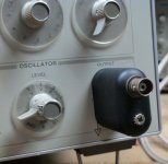
I decided the move to BNC connectors.
One of the shortfalls of the equipment of that period are those 4mm working terminal outputs (which aren´t really noise immune) which I converted to BNC with shielding skirts and 4mm lab pins, with a little soldering skill and tin plate. see pic. I can recommend this modification, as screened cable is really the right way to go.
The other is typical HP, no mains on indicator light, so I fitted a resistor/coloured LED to one of the test point outputs of the power supply to illuminate the gap around the mains switch. Also those 1000uF power supply electrolytics, which after nearly 50 years are ripe for a change despite the ripple still being ok. I am quite sure the more recent 79xx78xx series of regulators would fit the psu job perfectly as regards ripple rejection but I left the original as it functions fine.
The common mistake many users make is the trend to strip out all those interstage tantalum coupling caps...often unnecessary...That is a mistake as military grades were used which are very reliable and retain their very low leakage properties.
In all, the unit is still very much HP The slide rule designers of the era knew exactly, and internally often the least disturbed the better.
keep at it!
rj
Attachments
Though I agree that sometimes shielded ins/outs are needed, I prefer to retain the versatility of the binding posts, and use a shielded adapter when needed. In those situations the typical Pomona banana-BNC adapter doesn't cut it. These old GR 274-QBJ are perfect.
Attachments
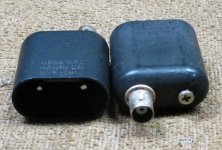
The GR's are great and hard to find (they must have been discontinued 30+ years ago). Pomona had a similar shielded adapter also really hard to find. Maybe someone will pick up on the opportunity?
The hardest and most important parts to find and own. Been doing audio since 1966. Having owned most of the important audio measurment devices since around 1957, you quickly learn that the specialized accessories, like these connectors and adapters are as important as the instruments they mate with...

- Home
- Design & Build
- Equipment & Tools
- Could use some help repairing my HP 339A