It's sad how the self-righteous are so quick to condemn, even the wrong people.
Yet so amazing when the self-righteous apologize to the "wrong people". Also amazing how you chose to overlook that part. Cheers!
Cool down chaps!
If you're on this early boat: be happy campers..
If you're eagerly waiting for the schematic/BOM: no offense: just wait until it arrives.;
In both cases I guess, we all have plenty of things to look at 🙂
Boards are here in FR now (received today), perfect packaging from Down Under (thanks a bunch for your efforts Stuart 👍), but still will have to wait early July to get all SCs
Enough time to focus on all the other bits🧐
Kal

Cool down chaps!
If you're on this early boat: be happy campers..
If you're eagerly waiting for the schematic/BOM: no offense: just wait until it arrives.;
In both cases I guess, we all have plenty of things to look at 🙂
Boards are here in FR now (received today), perfect packaging from Down Under (thanks a bunch for your efforts Stuart 👍), but still will have to wait early July to get all SCs
Enough time to focus on all the other bits🧐
Kal
This whole line of why the schematic isn't public domain RIGHT NOW is funny.
Some of us followed along from the beginning back in March of last year, ordered our boards months ago and just received them. For the math challenged, that was 15 months of reading about the amp and following the design before getting our hands on the schematic and some boards.
Learn some patience. You will get your turn.
If you want a schematic of Class AB power amp just google it or use the honey badger there are plenty of tested designs around, if your impatient and are desperate for this particular schematic which has been discussed for months on here you will just have to wait imhoI was the person who wrote the words "cash grab". I did not post again as I did not see any point in it. It's sad how the self-righteous are so quick to condemn, even the wrong people.
I stick with my opinion that the schematic should be made available. PCB cad files are not included in my opinion, just the schematic.
This is just an opinion tho.
Hi Guys,
For those who missed out on the first group buy. I have created a poll so we can see if there is enough interest to warrant 2nd group buy.
Group buy poll
please register your interest if you'd like a set of wolverine boards in the future.
For those who missed out on the first group buy. I have created a poll so we can see if there is enough interest to warrant 2nd group buy.
Group buy poll
please register your interest if you'd like a set of wolverine boards in the future.
Yeah I wonder how many group buys ?
Any way I've said all I will. Don't let my argument for making the schematic available make you think I'm desperate for this design.
If I'm honest even if the schematic was published, I would take 10 min to look at it, then never again. It's in principle I made my comments.
Regards
Any way I've said all I will. Don't let my argument for making the schematic available make you think I'm desperate for this design.
If I'm honest even if the schematic was published, I would take 10 min to look at it, then never again. It's in principle I made my comments.
Regards
^ If it's only out of curiosity and principle, one could look at many of the previously published schematics and BoMs. The latest tweaks (albeit important to eke out performance with a larger variety of somewhat readily-available parts) don't provide any additional insight into overall topology and design goals. They're (IMO) more of a service to those (like me) that could not/would not be able to accomplish those tasks on their own with a variety of semiconductors. Again, one of the goals stated fairly early on was to allow more builders more variety in their choices of semis and how to set up the amp to compliment their existing components (primarily speakers).
One reason to need the latest schematics / BoMs / Build Guides / Gerbers / Other various files - is to copy the design. To me, that goes against fairness. That's just one person's opinion. If another reason behind the principle is that the precise schematic and BoM must be known prior to purchase, that's a reasonable consideration. However, there have been enough schematics posted that are (dare I say) 99% complete. In addition, there were simulations of various configurations along with the as-built performance metrics of some configurations to make it (for me) an informed choice of whether or not to participate. There's also a post (I noted it previously) that contains a pretty darn accurate BoM. I used the information contained within those various posts along with the simulations to inform my choices and purchase a number of parts several months before the final schematics and BoMs were released to GB participants.
Either way, once the schematics and BoMs are more readily available (Again, it's my understanding that they will be) ... people that didn't want to take the leap early on, may have a chance later. Also for consideration, was that these boards would be available in the DIYA store. Personally, I am still waiting to hear any official word on the progress of that endeavor. By then, more people will have have a feel for the overall difficulty of the build, the cost of the build, and the performance of the build. That information may further entice, or it may detract, from the interest in the project.
Me, I just need to carve out some time to get on the bench.
Cheers!
Where is Pete? I hope he is well and will return to lead the project. Any ETA for the Spooky IPS?
Wolverine comes with a removable/replaceable front end board. The reasoning is to allow future front end developments or alternatives without the need to replace the whole amplifier. The EF3-4 version will accommodate a 50% longer front end board with space for regulators and opamps (shock/horror) for example.Where is Pete? I hope he is well and will return to lead the project. Any ETA for the Spooky IPS?
Last edited:
Nothing against Pete, but this project has been led over the finish line. It was from his brain and I respect that, but this project has matured in another direction, and I think, an amazing DIY success.
Jason, Stuart and the guys, pulled, spent, and sacrificed to mold Pete's' idea into something workable and functional. When people demanded, or spoke of money, I kept my thoughts to myself. I now break the mum. Hell, I had more than 3k out of pocket in the project. Ideas are good, but it takes an amazing amount of time, effort, love, and cash to get a design to the people. I don't think any of the project team is/was looking for a slap on the back, but it really chaps my *** when people demand something, or think they are owed something when they had nothing to do with anything relating to the project, just how is it you feel entitled to judge me/us because of your perceived entitlement, or some faux righteous indignation?
What projects have you put forth to the community, or do you simple give summary judgement?. Neil and I did the lion share of the testing. I have remained mute, but when people talk about cash grabs, or other motives, it just pisses me off. The team, and I have not had any contact in months, but if you think this was about money, you have missed the mark.
We struggled to get parts which would make this beast work, that is why the final values, and parts are/were not given. I'm the black sheep of the project, but I'm pissed by the arrogance of someone feeling they have a right to anything others have done. Ya know what people...? You aren't due anything from anyone at anytime.
In closing....
Do me a favor and get over yourself, if you have a problem with how I/We do things, then show us up and bless the community with your contributions.
Team Wolverine, thanks guys, it was one hell of a ride.
JT
Last edited:
The costs to complete this project were huge and 1000’s of hours were spent in this design. The team had to pay for prototypes, freight and components etc. Just one example, the freight alone for prototypes sent to Thimios was over US$200. Most of us live outside of the USA so we had to pay exchange rate variance and freight for the parts used in prototypes. Parts changed every two weeks. Anyone involved in design work would know this.
The team is out of pocket and will never recuperate the money spent. The trolls (who haven’t contributed) claim that this is a cash grab. How pathetic…
One guy had the audacity to send private emails to different team members to obtain the schematic and the Gerber files. I was told that he sells PCB’s in South East Asia.
It was clearly stated that this design will be published after the group buys. If you have any reservations in buying PCB's to build this amp, all you need to do is wait. There will be a lot of feedback, once amps are built.
has anyone started building this amplifier or not yet? I'll probably start working on it sometime in June.
A couple of questions:
Q107,108 - 2sc4793/2sa1837 are recommended but 2sa1859a/sc4883a are also acceptable but these have Vebo=6V not 5V, any adjustments needed?
what about using Sanken 2sa2223a/sc6145a as outputs?
cheers,
A couple of questions:
Q107,108 - 2sc4793/2sa1837 are recommended but 2sa1859a/sc4883a are also acceptable but these have Vebo=6V not 5V, any adjustments needed?
what about using Sanken 2sa2223a/sc6145a as outputs?
cheers,
has anyone started building this amplifier or not yet? I'll probably start working on it sometime in June.
A couple of questions:
Q107,108 - 2sc4793/2sa1837 are recommended but 2sa1859a/sc4883a are also acceptable but these have Vebo=6V not 5V, any adjustments needed?
what about using Sanken 2sa2223a/sc6145a as outputs?
cheers,
We tested the Sanken 2sc6145/2sa2223 but not with the 2sc4883/2sa1859. The 2sc4883/2sa1859 would be a great match with the Sanken outputs plus they have better SOA.
Remember when using 2sc4883/2sa1859 or 2sc4793/2sa1837 as drivers you'll have to limit the rail voltage to less than 64V for 4ohms and outputs need >70 hfe. If you have a difficult load or low hfe outputs you'll want to put in the mje15032/33.
No adjustments should be needed.
Jeremy
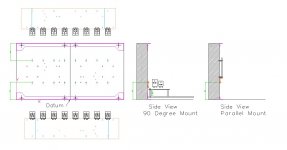
Me and Stuart are currently working together to add the holes for the Wolverine board in the best possible way to avoid misalignment or huge tolerance issues. We plan to drill both heatsinks together instead of drilling one at a time so this problem should be avoided.
Our idea was to center the layout on the heatsinks instead of having it shifted towards the bottom as in the Deluxe 5U chassis, I am attaching a screenshot to give you a better idea of what we are currently doing
Our idea was to center the layout on the heatsinks instead of having it shifted towards the bottom as in the Deluxe 5U chassis, I am attaching a screenshot to give you a better idea of what we are currently doing
Attachments
This is a great idea, cant wait to see what you guys come up with !Me and Stuart are currently working together to add the holes for the Wolverine board in the best possible way to avoid misalignment or huge tolerance issues. We plan to drill both heatsinks together instead of drilling one at a time so this problem should be avoided.
Our idea was to center the layout on the heatsinks instead of having it shifted towards the bottom as in the Deluxe 5U chassis, I am attaching a screenshot to give you a better idea of what we are currently doing
We tested the Sanken 2sc6145/2sa2223 but not with the 2sc4883/2sa1859. The 2sc4883/2sa1859 would be a great match with the Sanken outputs plus they have better SOA.
Remember when using 2sc4883/2sa1859 or 2sc4793/2sa1837 as drivers you'll have to limit the rail voltage to less than 64V for 4ohms and outputs need >70 hfe. If you have a difficult load or low hfe outputs you'll want to put in the mje15032/33.
No adjustments should be needed.
Jeremy
Side Note...
If the outputs hfe is 50 or greater the max rail voltage is 57V using those drivers (2sc4793/2sa1837 and 2sc4883/2sa1859) for 4 ohms.
Jeremy
Might want board space for double (same||same) electrolytic caps at 3 locations, small signal power, nfb shunt rc, and power board. That could reduce the bypass figure to picofareds or zilch. I mentioned it because making the amplifier more immune to cap swapping hijinks could be really labor-saving for audiophile builders. For example, replace Badger C4 with 220u (identical to C3), don't need to search for a "best-sounding" cap, and the amp doesn't need a servo.
I just had the same problem--didn't find badgers. But, I did find filenames that start with DIYA Perhaps the amp was named some time afterwards.. . . if anyone has the EXACT output device spacing for the Badger store boards ... please share. . I had to reverse engineer from the store PDF and a simple toner transfer image I had . I lost my original artwork.
Hi All, As people are talking about heatsinks has anyone made any calculations for the required thermal resistance needed for heatsink sizing?
All the best
Chris
All the best
Chris
- Home
- Amplifiers
- Solid State
- DIYA store "Wolverine" (Son of Badger) .... suggestions ??