Hi.
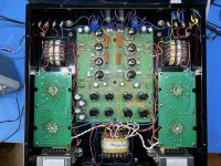
Well made tube power amplifer with 4 EL519 output tubes. One channel is playing with less volume. Cant figure out what is problem. Attached oscilloscope photo. Input signal generator with identical voltage. Changed tubes from one channel to another, no change. Input to first tube grille identical. Voltage to output transformer is different. It is about 26 years old. Attached photo from inside also.
Hoping somebody with more experience can give ideas what to check.
Thanks advance!
Attachments
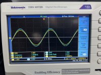
What does the scope show? Output of both channels?
Do you have a schematic?
Does this amp have global feedback? If not, such differences are not uncommon.
What are the blue things in the top of the picture near the input connectors, are these potmeters, level controls?
Do they adjust level?
Jan
Do you have a schematic?
Does this amp have global feedback? If not, such differences are not uncommon.
What are the blue things in the top of the picture near the input connectors, are these potmeters, level controls?
Do they adjust level?
Jan
Quick tests I'd do:
Then I'd get onto checking through the signal path vs the schematic. Not that I'm currently obsessed with caps and bode plots 😀 after my old 24yo amp's electrolytic lost enough capacitance to blow a 6.3A fuse due to ripple+inrush.
Pretty amp btw 🙂
- power transformer - check each side of the centre tapped secondary, also check the current draw from the power on each channel - that would possibly indicate those old electrolyte caps are starting loose capacitance and pull more power per cycle dropping the rail under load.
- output transformer - check, that would be the expensive issue to fix.
- bode plot on each channel - the response/phase should show any changes indicating a possible cap/resistor issue.
Then I'd get onto checking through the signal path vs the schematic. Not that I'm currently obsessed with caps and bode plots 😀 after my old 24yo amp's electrolytic lost enough capacitance to blow a 6.3A fuse due to ripple+inrush.
Pretty amp btw 🙂
Hi. Yes scope shows both channels, on output with 8 ohm dummy loads and voltage difference almost 20%.What does the scope show? Output of both channels?
Do you have a schematic?
Does this amp have global feedback? If not, such differences are not uncommon.
What are the blue things in the top of the picture near the input connectors, are these potmeters, level controls?
Do they adjust level?
Jan
Yes blue things are potensiometers for level and with theses can adjust to equal. It was before equal and now need to adjust 1/3 turn equal to. Thinking may be some component need to be changed.
Power for both channes coming from one supply and therefor it cant be problem, or I am wrong?
Last edited:
Thanks for ideas. As I understand from chematic jjasniew pointed (thanks) it has shared power filter caps, then both channels have same power. Cant be problem, or...Quick tests I'd do:
- power transformer - check each side of the centre tapped secondary, also check the current draw from the power on each channel - that would possibly indicate those old electrolyte caps are starting loose capacitance and pull more power per cycle dropping the rail under load.
- output transformer - check, that would be the expensive issue to fix.
- bode plot on each channel - the response/phase should show any changes indicating a possible cap/resistor issue.
Then I'd get onto checking through the signal path vs the schematic. Not that I'm currently obsessed with caps and bode plots 😀 after my old 24yo amp's electrolytic lost enough capacitance to blow a 6.3A fuse due to ripple+inrush.
Pretty amp btw 🙂
Do I check output transtormer simpli measuring winding ohm's?
I do not understand the third point. Can you explain more.
A 1dB difference is just barely noticeable under ideal conditions. Can you actually hear the difference? Loudspeakers are rarely better than within a few dB of each other; moving your head causes changes of many dB, etc. If this is an issue of different gain measurements, you'll have to get used to it; there will always be some difference, always. Yet we get by.
If you must track down the source of the 1dB imbalance, in a feedback amplifier the gain is mostly set by the ratio of resistors in the feedback network. Measure those and make both channels' ratios more similar. Note that I said "more similar" rather than "the same". There is no such critter as "the same". Tolerances.
All good fortune,
Chris

Looked up what is Bode plot and do I understand correctly: Will measure both channel's with different frequencies and see is there anomalies between channels?
For example 30, 250,1k,3k,6k and 12k and do the output voltage difference between channels changes?
For example 30, 250,1k,3k,6k and 12k and do the output voltage difference between channels changes?
Looked up what is Bode plot and do I understand correctly: Will measure both channel's with different frequencies and see is there anomalies between channels?
For example 30, 250,1k,3k,6k and 12k and do the output voltage difference between channels changes?
Basically the Bode plot shows what comes out vs what goes in, end to end. However it also shows phase change over frequency. As components alter the phase, if there's any issues that can appear as a difference between the two channel phases. Sort of a quick way to see if there's components per lapse being being non-similar before trudging through the schematic one by one. Some components are non-linear with volume but on the whole if you have the scope connected anyway it's a fast test. I would add 20K to the list simply to see the rolloff.
Chris' point on the feedback also a quick win as the first port of call on the schematic.
Do I check output transtormer simpli measuring winding ohm's?
Yes. A quick test. The windings should be showing the same or near to each other. If there's any shorts they can be visible but as Chris as pointed out 1dB isn't that much in the grand scheme of tolerances.
Thanks, Yes there is notable difference. I can turn down one channel and good with it. Same time it is interesting for me to find out what happened. Before volumes had same levels.A 1dB difference is just barely noticeable under ideal conditions. Can you actually hear the difference? Loudspeakers are rarely better than within a few dB of each other; moving your head causes changes of many dB, etc. If this is an issue of different gain measurements, you'll have to get used to it; there will always be some difference, always. Yet we get by.
If you must track down the source of the 1dB imbalance, in a feedback amplifier the gain is mostly set by the ratio of resistors in the feedback network. Measure those and make both channels' ratios more similar. Note that I said "more similar" rather than "the same". There is no such critter as "the same". Tolerances.
All good fortune,
Chris
Can you or other member point where is feedback on this circuit. circuit diagram from internet link here: http://www.troelsgravesen.dk/EAR-861.htm
Can usual resistors go out of initial resistance by time? I know that there must be some physical deformation by look?
No you're not wrong. The idea that differences in power supply capacitors would explain the difference in gain is, well, extraordinary.Hi. Yes scope shows both channels, on output with 8 ohm dummy loads and voltage difference almost 20%.
Yes blue things are potensiometers for level and with theses can adjust to equal. It was before equal and now need to adjust 1/3 turn equal to. Thinking may be some component need to be changed.
Power for both channes coming from one supply and therefor it cant be problem, or I am wrong?
I think you're all set. Don't fix it as it ain't broke.
Jan
Thanks. Will measure tomorrow.Basically the Bode plot shows what comes out vs what goes in, end to end. However it also shows phase change over frequency. As components alter the phase, if there's any issues that can appear as a difference between the two channel phases. Sort of a quick way to see if there's components per lapse being being non-similar before trudging through the schematic one by one. Some components are non-linear with volume but on the whole if you have the scope connected anyway it's a fast test. I would add 20K to the list simply to see the rolloff.
Chris' point on the feedback also a quick win as the first port of call on the schematic.
Last edited:
No you're not wrong. The idea that differences in power supply capacitors would explain the difference in gain is, well, extraordinary.
You're right looking at the schematic - a shared power supply would affect both. I assumed (my fault) that it was split with separate rails for each channel.
Thanks for everyone for pointing out ideas. I liked also Jan remark "Don't fix it as it ain't broke" Actually it works very well and input potentiometer can level volumes.
One question more:
I know that capacitors have lifetime and heat inside tube amplifier has influence on theses also. Is it good idea to change all electrolyte capacitors, as this amp is made 26 years ago? I have used it some years and quite intensively.
One question more:
I know that capacitors have lifetime and heat inside tube amplifier has influence on theses also. Is it good idea to change all electrolyte capacitors, as this amp is made 26 years ago? I have used it some years and quite intensively.
A 1dB difference is just barely noticeable under ideal conditions. Can you actually hear the difference? Loudspeakers are rarely better than within a few dB of each other; moving your head causes changes of many dB, etc. If this is an issue of different gain measurements, you'll have to get used to it; there will always be some difference, always. Yet we get by.
If you must track down the source of the 1dB imbalance, in a feedback amplifier the gain is mostly set by the ratio of resistors in the feedback network. Measure those and make both channels' ratios more similar. Note that I said "more similar" rather than "the same". There is no such critter as "the same". Tolerances.
All good fortune,
Chris
Chris, thanks. Your replay put me thinking about calculations. Could you please explain barely noticeable 1 db difference you wrote. I see that with exact same voltage input, amplifier output voltage is 3,08 and 3,64. By ohms law it is 0,38 and 0,45 amps with 8 ohms dummy loads. Power will be then 1.17 and 1,64 watt's respectively. It seems big difference. Of course it can be adjusted with input but can it be taken then as normal with tube amplifiers?
Connected speakers are high sensitivity 94 db, maybe because of this I hear difference. More speaker sensitive, more you hear channels difference in small room environment ...?
I am not so good in English, sorry advance.
Thanks
Rait
This amp has two important gain-setting feedbacks. The first is the input diff stage's degeneration resistor (10K Ohm). These need to be pretty close to the same for each channel. The second is the ratio of the three-in-series 39K resistors to the 3K9 cathode resistors that they're feeding. These need to be as close as possible to "the same" for all four ratios. I'd look hard at the 39K resistors because they've been running the warmest.
All good fortune,
Chris
All good fortune,
Chris
- Home
- Amplifiers
- Tubes / Valves
- Problem with old tube amp