
Truly inspirational build quality.few more details I forgot:
- ZM is Chicken - 20K multiturn trimpot instead of enclosed 25K FABPa model
-washer + split washer everywhere
-heatshrinking wire ends leads to nicer look; it also increase your Zen
-toss enclosed crimping connectors in trash bin; solder everything; it also increase your Zen
-soldering of sensitive plastic parts - crank station to max, do it fast and efficient - funny but lesser melting of plastic that way
-enclosed nice dome head screws - while M3, having 'Merican Allen key head - who invented that shizo thing - ZM Is not having 'Merican Allen wrenches in appropriate quality, so I can't tighten them properly ..... anyway - stainless steel headless screws and nuts are much better for T Bar tightening ..... even if inadequate
-drilling of 4.2mm holes for additional M4 Allen key screws- sorta mid of T Bar length, use calipers to b precise enough to situate them exactly in between the heatsink fins; drill heatsink first, then mark through these holes points on T Bars
-dissipation of mosfet is 1A8*(14V-(1A8*0R75))=22W77
-dissipation of VFet is (36V-(1R1*1A8)-14V)*1A8=36W04
-summ dissipation per channel , including PSU, is 1A8 x36V=64W8
go figure - 128W of heat for 2x10Wrms
aaaaaaalmost SIT-2 Territory

I had one question about how you terminate your bare wire (See bold above). Are you using some type of pin termination then heatshrinking over pin or is that just bare wire that's tinned with solder and then heatshrink over remaining uncovered wire once solder to boards? I've seen this on all of your builds and they seem like a very solid and clean connection.
Thoroughly well done ZM.
I will look into performing the psu board surgery to get the relay working. Thanks for sharing.

I will look into performing the psu board surgery to get the relay working. Thanks for sharing.
@CoGT3
my pcbs, power traces, pads on them - all having ~2mm Dia hole, so I'm using needle end wire crimp connectors, supposedly 2.5mmsq; adequate for all wires from 0.75 to 4mmsq
always removing plastic sleeve from them, gentle crimp on bare wire end, then soldering wire and connector together ........ so crimping is just to have it mounted and basic physical contact, solder doing majority of job
then heatshrink all, solder needle pin to pcb, cut
on non - power-traces on my pcbs, I'm simply removing wire isolator on end of wire, mount heathsrink as sleeve, then either pre-tin or solder ditto on pcb
doing exactly the same on all pads on no-mine pcbs, rare case that pad is made for needle end connectors
started heatshrinking almost everything - hate to see even sightly melted isolation; not all wires are having PTF isolation or ultragigamega non-melting plasticky
did contemplate using so called wire sleeves for end dressing - but that's just unnecessary complication - good for screwed connections in pro field, which I'm not using and never will

-enclosed nice dome head screws - while M3, having 'Merican Allen key head - who invented that shizo thing - ZM Is not having 'Merican Allen wrenches in appropriate quality, so I can't tighten them properly ..... anyway - stainless steel headless screws and nuts are much better for T Bar tightening ..... even if inadequate
Nota bene, it turns out that "torx" style bits will fit a lot of hex head / Allen head bolts pretty cleanly, with minimal if any slop. The little bolts in the Modushop Mini Dissipante kits that fasten the top plates are one such example that I use the next to smallest torx bit in this picture on exclusively.
Attachments
well, when speaking of force necessary here, that fitting isn't good enough ..... though main reason why I didn't use those M3 is realization that M3 is simply no go in entire mechanical/thermal arrangement
that's why I resorted to what is shown - brute force with genuine 8.8 screw hardware of appropriate size
was lazy, solved everything with two additional through-hole M4, proper quality, so tightened with force - mechanical terms ...... (say 2Nm as minimum), not electromechanical
electromechanical....... that being field where 1.3Nm is more than enough, dealing with transistor cases, thermal pads etc
speaking of sweet dome-head M3 screws, wanted to use them for top cover, but didn't - exactly because of 'Merican Allen size; so used SS Metric with SS washers, good enough looking
👆
Thank you for the detailed response. I'm going to hunt down some of those crimp pin connectors to try with Randy's V8 PS boards. Suspect they will be awfully close.
Thank you for the detailed response. I'm going to hunt down some of those crimp pin connectors to try with Randy's V8 PS boards. Suspect they will be awfully close.
And here I was thinking that I was the only one not finished. 😉This is the sort of hand holding I need to finish this amp. Thanks, ZM!
jeff
ZM have you note that the green resistor are heating che elco on psu pcb quite a lot ?
Datasheet math can help create useful estimates.
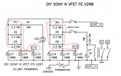
Assuming the PCB is stuffed with six pieces of the green Vishay resistors, Mouser part number 594-AC050003308JAC00 (3.3 ohms , 5 watts , 7.5 x 18 mm) ... then
ZM measured 1.8 amperes DC per channel. Each channel is fed from three 3.3R resistors in parallel, so each of the three resistors carries one-third of the current, namely (1.8A / 3) = 0.6 amperes.
Resistor power dissipation is I * I * R and in this case that's 0.6 * 0.6 * 3.3 = 1.19 watts. Each of the six green resistors is dissipating 1.19 watts. Together the six of them form a linear array of heat emitters.
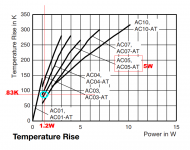
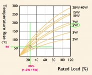
Mouser has a link to the engineering datasheet from Vishay, and on page 8 of that datasheet we find the graph below. It says that when an AC05 (5 watt) resistor dissipates 1.19 watts, its body temperature rises to 83 Kelvin above the ambient air temperature. If the air temperature is 30 degrees Celsius then the resistor body will be at 113 degrees Celsius. Hot enough to boil water, hot enough to burn your finger. Hot enough to cook the nearby electrolytic capacitors? Use an FLIR / infrared camera to investigate further.
_
Attachments
Last edited:
ZM is ChickenZM have you note that the green resistor are heating che elco on psu pcb quite a lot ?
but with time I really did learn to not argue Papa's choices
that's the reason why I didn't replaced 1R5 , to elevate them
3R3 at PSU, nothing critical
again, who had a look at Musical Fidelity wonders.... everything else is sheer breeze
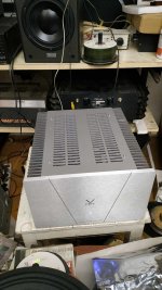
That all nude aluminium build, and barely okey soldered 😉 electronic components looks very very nice. For real.
Somehow VFEt text and black stripes fukkes the whole ting up, and also looks really pro good. At the same time.
Less is more. And. More is more. Strange🙂
Somehow VFEt text and black stripes fukkes the whole ting up, and also looks really pro good. At the same time.
Less is more. And. More is more. Strange🙂
finger tell me 55° at last on top of alu caps plus a bad smell of resistor body....as suggest from ZM a metal body on ampDatasheet math can help create useful estimates.
Assuming the PCB is stuffed with six pieces of the green Vishay resistors, Mouser part number 594-AC050003308JAC00 (3.3 ohms , 5 watts , 7.5 x 18 mm) ... then
ZM measured 1.8 amperes DC per channel. Each channel is fed from three 3.3R resistors in parallel, so each of the three resistors carries one-third of the current, namely (1.8A / 3) = 0.6 amperes.
Resistor power dissipation is I * I * R and in this case that's 0.6 * 0.6 * 3.3 = 1.19 watts. Each of the six green resistors is dissipating 1.19 watts. Together the six of them form a linear array of heat emitters.
Mouser has a link to the engineering datasheet from Vishay, and on page 8 of that datasheet we find the graph below. It says that when an AC05 (5 watt) resistor dissipates 1.19 watts, its body temperature rises to 83 Kelvin above the ambient air temperature. If the air temperature is 30 degrees Celsius then the resistor body will be at 113 degrees Celsius. Hot enough to boil water, hot enough to burn your finger. Hot enough to cook the nearby electrolytic capacitors? Use an FLIR / infrared camera to investigate further.
_
heatsink will be better. Btw not a big problem....
That's one reason why my re-implementation of this board uses rectangular, cement-block packaged, 5 Watt resistors: to achieve lower body temperature rise @ 1.19 watts per resistor. See Figure 1 below: temperature rise is 56K rather than 83K for the green cylindrical resistors as in post #30.
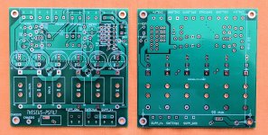
Gerbers and schematics for this board are on the Forum and freely downloadable; it's called the Ship Of Theseus PSFILT. Builders who despise Euroblox connectors can, of course, omit them and solder directly to the PCB instead.
The 5W resistors' Mouser part number is 603-SQP500JB-3R3. Oh by the way, the PCBs have a pair of air vents / cooling holes in each 5W resistor footprint, which has zero cost and nonzero benefit.
_
Attachments
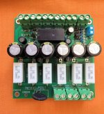
Those photos show the high frequency filtering enhancements that I added to the PSFILT board. Each channel's power supply gets a ferrite bead (28C0236-0EW-10) (R)LC filter, and also an inductor (RL622-100K-RC) LC filter, for greater attenuation of SMPS noise. PCB footprints are labeled FB1,2 and L1,2 in the photos.
Frankly, I was thinking of further gilding of lily
ditching existing RC filtering, including CLC filter per channel, with existing ZM choke model shown in https://www.diyaudio.com/community/threads/ludef.369990/post-6997306
but knowing my bastardy nature, it would only lead to drilling another hole in the back, adding another Mean Well PSU, so having benefits of each brick feeding half of load, and truly dual mono
anyhow, with time, I did learn that things are best when everything is properly tinkered from the start - this little amp is perfect already, with some OCD involved in assembly and slight trick in delay circ
as I'm being already blessed with numerous Papa's personal gifts, that didn't blocked my salivating and warm feeling around me heart, even if amp itself isn't actually belonging to me
little jewel is little jewel - hard to make it better with further polishing
if you want bigger jewel, just make it bigger, from the scratch
- noting against tinkering and initiative - it is very core of Papacrumbs; just saying that - in this format - whatever one does, possible improvements are not night and day difference; everything can be just different sprinkle on already rich cake


- Home
- Amplifiers
- Pass Labs
- Lottery DIY Sony VFET pt 2 (N-Channel) - assembly by Mighty ZM