oh, dear. I must apologize. Didnt' mean to create that much work.
When I mentioned testing each section, it was to remove the jumpers and connections to the next section.
In other words, remove the jumpers between the diode board and the filter board then try. Then reconnect the diode to filter jumpers but make sure the filter board isn't hooked up to anything on it's outputs (no ground, no signal boards) and test. All the while, testing each step not just if the transformer is buzzing but also what your voltages are.
However, with the extra work, can now test the resistors and any other components (LEDs, caps, thermistor, etc.) that your MM or other test equipment will support.
Yes, most likely will hear a slight buzz when right up on the transformer. The 10 feet hearing distance is not expected.
I was wondering why you said that so cavalierly 😉. JK and regardless, I think it’s cleaner to do it this way.oh, dear. I must apologize. Didnt' mean to create that much work.
When I mentioned testing each section, it was to remove the jumpers and connections to the next section.
In other words, remove the jumpers between the diode board and the filter board then try. Then reconnect the diode to filter jumpers but make sure the filter board isn't hooked up to anything on it's outputs (no ground, no signal boards) and test. All the while, testing each step not just if the transformer is buzzing but also what your voltages are.
However, with the extra work, can now test the resistors and any other components (LEDs, caps, thermistor, etc.) that your MM or other test equipment will support.
Yes, most likely will hear a slight buzz when right up on the transformer. The 10 feet hearing distance is not expected.
Step 3: ✅ and no hum.
just need to wait for the capacitors to drain and will hook up the ground.

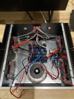
Yar. Would've been nice to find the culprit but got the desired result. Hopefully the music is flowing?
Yeah, agreed. The music is flowing. I'm setting the bias/offset now.Yar. Would've been nice to find the culprit but got the desired result. Hopefully the music is flowing?
Asking for a spec check before I start soldering:
Diodes:
IXYS DPG60C300QB
Peak Reverse Voltage: 300V
Max Surge Current: 360A
If - forward current: 30A
Recovery Time: 35ns
Vf - forward voltage: 1.06V
Heatsinks:
Aavid 513201B02500G
2.0W @ 20°C
Key question - is the heatsink good enough? Wanted to get the 2.5" tall version but only found the 2" tall version in stock.
Any help/advice on how to determine amount of 'sink needed would be great.
This is for a pair of 1stW clone (F5 or F6) amps running as balanced monoblocks.
Attachments
Hi. I do not have the best math/physics background, nor do I have the setup to measure inductance. For f5 turbo v3 fed by 25VDC, could someone provide me approximate values of RS1 and 2, as well as CS1,2 CX1,2 ?
Never mind, found the answer.Hi. I do not have the best math/physics background, nor do I have the setup to measure inductance. For f5 turbo v3 fed by 25VDC, could someone provide me approximate values of RS1 and 2, as well as CS1,2 CX1,2 ?
Noobie here with a troubleshooting question. I'm testing my PSU with a bridge rectifier and I get the expected -24V DC at the output of my negative rail. But I'm only getting 2.4V DC on the positive rail. Any idea what could cause this? Pics attached
Attachments
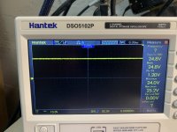
Measuring it on a scopeenough of a coincidence, is the meter not set to the right magnitude?
Here's what you may consider doing to narrow it down, if you're confident in your measurement. It's a relatively simple circuit, so you can figure it out quickly, I'd hope.
Use the same monolithic rectifier - don't hook up the filter board. Measure the "uncleaned"/rippled - DC. Record the value.
Check your other monolithic rectifier w/o the filter board. Use the same secondary. Same measurement.
Now do the same thing with the other secondary.
If everything is in the proper neighborhood of your rails, then move along. If not, then you've narrowed it to a rectifier and/or at least one secondary winding of your transformer.
Hook the filter board up to the rectifier you'll use for positive. Measure and record V+
Hook the filter board up to the rectifier you'll use for the negative. Measure and record V-
If you still only get 1/10th the voltage from the positive rail with the filter board, send more pics of the front and back of the board. It seems to be stuffed correctly, but a bad joint and/or one of your blocks may be part of the issue.
It does not directly relate to your question, but 25V caps are on the edge with that configuration.
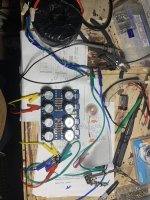
Thanks so much for your help. Something very odd is going on. I get 18V AC out of both secondaries as expected. But when I hook them to rectifier and measure the DC outputs, I get a pulsing DC of between 64-68 VRMS. this happens on every combo of both rectifiers and both windings. Is this rectifier model some kind of amp?? See attached pics.
Attachments
-
 8D803AFC-670D-43AD-807B-04A7CA2FEDA0.jpeg447.7 KB · Views: 121
 -
 780B77C0-281E-44AF-ABC9-C8C16F359543.jpeg383.3 KB · Views: 123
 -
 374E59FA-E91B-4EBC-BC67-DA53E22592D4.jpeg477.8 KB · Views: 136
 -
 2A75925A-ED66-4653-87D3-43CE2163BAA5.jpeg501.7 KB · Views: 134
 -
 A60DC06C-14ED-4807-A3E0-EDF58A0627DC.jpeg233.9 KB · Views: 138
 -
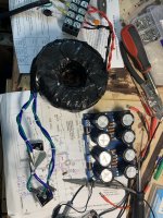 image.jpg640.5 KB · Views: 134
Start at the beginning.
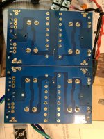
In your last picture you show the bridge wired to the transformer. If you connect the output of that bridge correctly to the board (so it connects across R9 and C3) what DC voltage do you measure on a DVM on DC volts across C3?
If you think you have a weird issue somewhere then I would suggest using a DBT (dim bulb tester) to prevent any large currents flowing. Use a really low wattage bulb.
Is your line voltage 120 or 240?
Did you measure your secondary voltage with the transformer alone or with the primaries wired into the thermistors and connection block?
If your line voltage is 240V, you may have miswired the primaries in parallel and doubled the secondary voltage.
For simple AC voltage measurements, a multimeter is the simplest and easiest instrument to use.
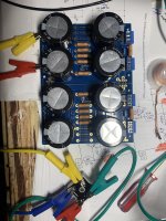
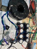
Line voltage 120V. Secondaries measure at 18v both direct to the wall and with thermistor block. I just hooked up bridge to positive rail as shown and I don’t get any DC across C3. But I do get the fully rectified 25v DC at the DC outputs of the bridge.
Attachments
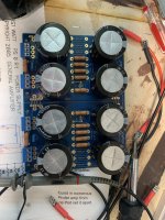
Looking at your photo of the underside of the PS board (post #1,894), the soldering needs a lot of rework. Many of the joints do not have enough solder, and most likely not enough heat was applied. You need to redo the solder joints.
Ok I will do that.Looking at your photo of the underside of the PS board (post #1,894), the soldering needs a lot of rework. Many of the joints do not have enough solder, and most likely not enough heat was applied. You need to redo the solder joints.
As you are using a scope that shows (confirms) that you are seeing not just rectified AC but AC that is rectified and smoothed. If you have no voltage across C3 then you must have an open circuit connection somewhere. You should see the same 25 volts across R9.But I do get the fully rectified 25v DC at the DC outputs of the bridge.
- Home
- Amplifiers
- Power Supplies
- diyAudio Power Supply Circuit Board v3 illustrated build guide