I saw that. Unbelievable that you can market a product with low single digit OL margins when 26 dB is so easy to achieve. JA is far too polite.https://www.stereophile.com/content/emt-128-phono-preamplifier-measurements
Another expensive phono stage with pathetic overload margins...
Getting these overload margins, output levels and distortion figures Is not rocket science - it’s just good engineering. We’ve given JC a hard time on occasion, but his phono stages in general are pretty state of the art. Of course he prefers all discrete to achieve these performance levels, but you can get pretty close with good opamps or hybrid (discrete + opamp).The sad EMT unit overload margins as stated in the Stereophile review:
"Even at the lower gain setting, the EMT 128's overload margins were on the low side, at 9dB at 20Hz, 8.3dB at 1kHz, and 3.5dB at 20kHz, all ref. the nominal MC level of 1kHz at 500µV. These margins were all reduced by 6dB at the higher gain setting."
Here are the specs for the Pass xOno (misstated as Aleph, although I think it is the same circuit) in it's Stereophile review:
"The Aleph Ono's MM phono overload margin is good; using an unequalized input, 1% THD+noise was reached at an input of 203mV (32.2dB overload margin ref. 5mV) at 1kHz, 1.9V (31.5dB) at 20kHz, and 17.3 mV (30.8dB) at 20Hz. The corresponding MC figures are 19.8mV (32dB overload margin ref. 500µ;V) at 1kHz, 201mV (32.1dB) at 20kHz, and 1.7mV (30.6dB) at 20Hz—all excellent figures."
And the Pre I would love to own, the Vendetta has fabulous specs including overload margin, once again here from the Stereophile review:
"The measured overload margins (ref. 0.5mV at 1kHz) were among the best I have ever measured, at 32.75dB at 20Hz, 31.6dB at 1kHz, and 29.4dB at 20kHz. The output level at the 1% clipping point was more than 15V! To sum up, this superbly uncompromised measured performance is a tribute to the Vendetta's designer."
Weird EMT would have released a circuit with that performance deficit. And at over 4 times the cost of the Pass in it's machined aluminum case...go figure.
Cheers,
Howie
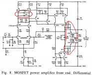
Ah, that text clears things up a bit. Reference of 2 mV and midband gain of 23.5 dB; there's your factor of ~ five difference between gain of 47 and gain of 47 dB. 23.5 + 47 dB gain over 2 mV is far easier to achieve with a 24V rail than 77 dB re: 5 mV.Have another look at Figure 1. The "Disc Amplifier" is followed by the "Normalization Amplifier", which increases the end-to-end gain. Disc amplifier gain is 23.5 dB at 1 kHz and overload is quoted re: 2 mVrms . Remember it was 1976.
_
I must confess that my sense of typical cartridge output levels was developed long after 1976.
A mid band gain of 23.5 dB and ref 2mV input really shows that preamps vintage. Most phono pre’s nowadays are spec’s at 5 mV or thereabouts input, 35 dB gain at 1 kHz followed by 14-16 dB line level gain for circa 1 V out to the power amp. A few may provide additional switch selectable gain to give a few dB extra. The S/N and noise floor on a specified 2mV MM input would suffer in a modern context. It also has to be remembered that Brit power amp stages from the 1970’s would give full output with c. 350 mV (some even lower) input so this would explain Self’s gain structure.
There actually is a very good case for not too much headroom. If you drop the stylus onto the record you will get a large signal. It the preamp has lots of headroom and the following amplifier has lots of reserve power, you may just need new loudspeakers!
Yes, this 47dB is just a rather meaningless figure for the first stage.Have another look at Figure 1. The "Disc Amplifier" is followed by the "Normalization Amplifier", which increases the end-to-end gain. Disc amplifier gain is 23.5 dB at 1 kHz and overload is quoted re: 2 mVrms . Remember it was 1976.
_
In the second stage the signal has to be amplified some 20dB to get the usual 40dB min gain for an MM amp.
That will reduce the 47dB to 27dB OM.
Hans
On a re-read I do wonder about the way JA is measuring overload margin. He states that overload is defined as 1% THD (same as the measure he uses for power ratings on PA tests). Now most phono stages will have very low THD until close to clipping so I wonder what the EMT does if you keep pushing the level up? let's face it 1% THD is still way under that coming off the record so might not be that noticable....
I have never, NEVER, EVER dropped a stylus on a record...NEVER!!! EVER!!There actually is a very good case for not too much headroom. If you drop the stylus onto the record you will get a large signal. It the preamp has lots of headroom and the following amplifier has lots of reserve power, you may just need new loudspeakers!
That said, I did catch my sleeve on the tonearm of the record playing at the time in the nightclub I DJ'd at, dragged the needle across the record..
I thought lightning had hit the building..
Everybody looked at the DJ like he was an idiot.. And, I was unable to disagree..
Sigh, the good old days..
How goes it? My new toys...laser CNC, glass kiln.. havin fun
John
But less headroom than some records have as signal doesn't seem clever...There actually is a very good case for not too much headroom.
@jneutron was reading Cern is firing up Hilumi soon. I hope they remembered your soldering lessons!
Might actually be preferable to have "only" ~25 dB overload margin PLUS antisaturation clamp circuits sprinkled throughout the preamp upstream stages, like the Cordell JAES paper. Now the worst an overload can do, is send the preamp into clean clipping and clean recovery, without rail sticking or other artefacts.
_
_
Attachments
We are making upgrade quads for it. At the moment, working through a violation of Faraday's law of induction.. Somebody designed a structure that sits inside a high gradient field that can collapse very quickly during a magnet quench, resulting in multi-kiloamp currents (actually, tens of kiloamps) and huge lorentz forces. Sigh, there's never an EM physicist around when you need one.But less headroom than some records have as signal doesn't seem clever...
@jneutron was reading Cern is firing up Hilumi soon. I hope they remembered your soldering lessons!
Having fun with my day job...(hint for anybody who understands chemistry and electrolysis....comments welcome..)
Recruited in to solve an electrolysis issue in a very big machine. Orifices clogging, magnets overheating...
Seems the anodes in the electrolytic cells within the water cooling system are building up CuO at a large rate. Plugs up the water channels.
Cathodes are building Cu2O, but at a smaller rate. Water is 2 meg-ohm DI, oxygen is very low.. Looks like 2 v/cm gradients are max, 20 and 24 v/cm just makes too much oxygen and fittings clog quickly. Also seems we are not the only nat lab with the issue...
comments needed.. and welcome..
JN
I'm presently fighting electrochemistry on a semi-daily basis, but please don't trust me. Not sure where the copper is in relation to these electrical paths.
Water against Cu, no matter the purity (actually going to be more potent with higher purity) is going to etch/attack. No passivation of the copper, no inhibitors?
Water against Cu, no matter the purity (actually going to be more potent with higher purity) is going to etch/attack. No passivation of the copper, no inhibitors?
Dang,We are making upgrade quads for it. At the moment, working through a violation of Faraday's law of induction.. Somebody designed a structure that sits inside a high gradient field that can collapse very quickly during a magnet quench, resulting in multi-kiloamp currents (actually, tens of kiloamps) and huge lorentz forces. Sigh, there's never an EM physicist around when you need one.
Having fun with my day job...(hint for anybody who understands chemistry and electrolysis....comments welcome..)
Recruited in to solve an electrolysis issue in a very big machine. Orifices clogging, magnets overheating...
Seems the anodes in the electrolytic cells within the water cooling system are building up CuO at a large rate. Plugs up the water channels.
Cathodes are building Cu2O, but at a smaller rate. Water is 2 meg-ohm DI, oxygen is very low.. Looks like 2 v/cm gradients are max, 20 and 24 v/cm just makes too much oxygen and fittings clog quickly. Also seems we are not the only nat lab with the issue...
comments needed.. and welcome..
JN
It has been a few years since I was specifying chiller water treatment....I do know that nitrate treatment was necessary to keep the copper cathodes and anodes from eroding in our plasma metalizers. Once you add ionic substances like nitrates to the H2O you need to control the leakage currents. We passed all chiller lines through grounding fittings at each machine, keeping circulating currents down between machines.
Plain DI water 2-11 Mohm is going to eat most metals, we had stainless steel fittings disappearing at an alarming rate in our 11 M polished DI H2O system...we had Teflon wherever possible. If I remember anything else (it was 9 years ago...) I'll speak up.
Howie
Nice set of measurements here on the new Luxman m10x amp:-
https://www.stereophile.com/content/luxman-m-10x-power-amplifier
https://www.stereophile.com/content/luxman-m-10x-power-amplifier
We are running at 2 megohm-cm. Unfortunately, some of the manifolds are 20 v/cm, some at 24 v/cm, and they buildup very quickly.Dang,
It has been a few years since I was specifying chiller water treatment....I do know that nitrate treatment was necessary to keep the copper cathodes and anodes from eroding in our plasma metalizers. Once you add ionic substances like nitrates to the H2O you need to control the leakage currents. We passed all chiller lines through grounding fittings at each machine, keeping circulating currents down between machines.
Plain DI water 2-11 Mohm is going to eat most metals, we had stainless steel fittings disappearing at an alarming rate in our 11 M polished DI H2O system...we had Teflon wherever possible. If I remember anything else (it was 9 years ago...) I'll speak up.
Howie
Even the locations running 4 and 6 v/cm are problematic. It looks like below 2 v/cm is going to work. I'm trying to get them to adopt a 1v /cm design nominal.
They are considering taking the water to 6 or 8, but I'm cautioning them on copper dissolution rate, I can't find any graph showing copper loss rate with resistivity.
John
From day 1 it's just been DI at 2 megohm-cm with no added ingredients. Most of the magnets are made with hollow copper conductors, with cooling water running through them. Most of the magnets have multiple cooling loops in parallel and multiple coils in series. A plastic manifold (PEEK) distributes the water while isolating the coils electrically.I'm presently fighting electrochemistry on a semi-daily basis, but please don't trust me. Not sure where the copper is in relation to these electrical paths.
Water against Cu, no matter the purity (actually going to be more potent with higher purity) is going to etch/attack. No passivation of the copper, no inhibitors?
At day 1, the dipoles were running with 400 volts to ground with only 1 cm of isolation. Probably lasted about 20 minutes... They inserted hoses and upped the isolation distance to 20 cm, giving 20 v/cm. That lasts about a year, then they had to take various distribution manifolds apart and clean the stainless fittings of buildup of CuO. The quad manifolds run 6 v/cm max and are now giving us problems. The sextupoles were running 24 v/cm and have been an issue for years now. A 3 month trial with 30 cm isolators (.8v/cm) has proven perfect, and I'm fighting for a design criteria of 1 v/cm, 2 max.
We are now running a trial on a dipole with 2 meter hoses giving 2 v/cm, I bonded the hose fitting to the most positive points on the magnet as I realized that there were actually two electrolysis cells in series because of the intermediate stainless fitting. The bond eliminates the cell in the manifold. We are also considering smaller diameter hoses to reduce the cross sectional area of the water column to increase the column resistance.
We don't have actual copper electrolysis due to voltage gradients, the copper is always an inch or so away from the leading edge of the conductor,. The compression fittings are 316 SS, so the E field can't reach the copper. Five diameters into a conductive tube, the gradient field has dropped to nothing.
However, the DI does attack the copper, so the copper ions in solution will aggressively bond to the oxygen being generated at the positive potential fittings (anodes) hence the quick buildup of CuO. I also worry that the more copper we deposit, the more gets pulled from the magnet coils. Eventually, we may need to changeover to 30 thousand gallons of prestone antifreeze to close all the pinholes.
jn
Hye John,We are running at 2 megohm-cm. Unfortunately, some of the manifolds are 20 v/cm, some at 24 v/cm, and they buildup very quickly.
Even the locations running 4 and 6 v/cm are problematic. It looks like below 2 v/cm is going to work. I'm trying to get them to adopt a 1v /cm design nominal.
They are considering taking the water to 6 or 8, but I'm cautioning them on copper dissolution rate, I can't find any graph showing copper loss rate with resistivity.
John
As I am sure you know, the issue is balancing cations and anions for specific metal preservation. This is where working with a chiller water treatment specialist if you aren't already is a good idea, they have different formulations for different purposes. Chemistry in cooling water is a pretty advanced science, between antibiological agents, pH balancing and anti-corrosives potentially all competing for the same ions. I don't know your specific application, maybe none of this is relevant...
Cheers!
Howie
It is a 800 meter circumference synchrotron light source. It has roughly 1000 water cooled magnets. The issue is the voltage gradients at the magnet manifolds. Too high, and bad things happen. It looks like staying below 2 v/cm with 2 meg water will last way past my "use by" date.Hye John,
As I am sure you know, the issue is balancing cations and anions for specific metal preservation. This is where working with a chiller water treatment specialist if you aren't already is a good idea, they have different formulations for different purposes. Chemistry in cooling water is a pretty advanced science, between antibiological agents, pH balancing and anti-corrosives potentially all competing for the same ions. I don't know your specific application, maybe none of this is relevant...
Cheers!
Howie
However, you mentioned 11 meg as attacking stainless, that is a really good point that I will take back to the guys.
We are using 316 SS fittings, do you know what type you were losing?
All comment I see you make are relevant, thank you. The only reason I'm in this is because they've been wrestling with the blockage problem for three years now, so my boss tossed me under the bus. It's taken two months to get the other guys to even understand that it's the gradients that are killing them.
I even had to get someone to understand that the electrolysis current was dependent on the hose diameter.
JN
Hi John!It is a 800 meter circumference synchrotron light source. It has roughly 1000 water cooled magnets. The issue is the voltage gradients at the magnet manifolds. Too high, and bad things happen. It looks like staying below 2 v/cm with 2 meg water will last way past my "use by" date.
However, you mentioned 11 meg as attacking stainless, that is a really good point that I will take back to the guys.
We are using 316 SS fittings, do you know what type you were losing?
All comment I see you make are relevant, thank you. The only reason I'm in this is because they've been wrestling with the blockage problem for three years now, so my boss tossed me under the bus. It's taken two months to get the other guys to even understand that it's the gradients that are killing them.
I even had to get someone to understand that the electrolysis current was dependent on the hose diameter.
JN
I think we only used 316 SS Swagelock fittings, etc. We used their dielectric separators where things were hard-piped: https://products.swagelok.com/en/fittings/dielectric-fittings/c/108?clp=true
The only way to have a system with so many liquid connections leak-free was to use their system with torque gauges and train techs to use them.
Good luck with this issue; we had excellent service with our plasma target cathode cold-plates and anode/magnet coolers with the full suite of chiller additives. On the other hand our 11 M ohm system was entirely intolerant of any metal fittings. The 11 M ohm system was of course a continuously polishing loop through mixed DI beds because a certain percentage of water wants to become H and OH so damn badly!! The loop extended all the way to the tips of the spray nozzles in order to ensure ion-free water, even at the first nozzle opening. Optical disc manufacturing was a really tech-intensive way to make dirt-cheap disposable consumer trash....I mean high-quality CDs and DVDs.
I going to bed, GN!
Howie
- Home
- Member Areas
- The Lounge
- The Black Hole......