Ok, finally some noteworthy update.
I received my UMIK-1 microphone and I could not wait until the final missing exciters arrive and decided to do some testing with the other 4 exciters, that I already have.
So, the setup was like this;
Two guitar braced 3.2x4ft rev ply panels with exciters in different positions for better comparison.
Panel 1 had the two exciters on the blue markings, which are two of the epoxy filled carved spots.
Panel 2 had the exicter at the red markings, where nothing was done to the wood surface.

I have never done something like that before and forgot during the first test to upload the calibration file for the microphone,... therefore I have no idea how reliable the following picture is.
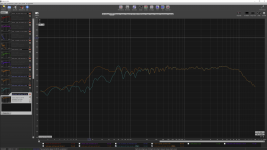
all following graphs are done with 1/12 of an octave smoothing,.. I hope that is ok/standard here?
I placed the mic 40cm from each panel and did a sweep and tried to compare the positioning of the exciters on both panels. (pink curve, is the red exciter position, and red curve is the blue exciter positions). The subwoofer on the ceiling was turned off.

This was truely a surprise and my first thought was : "What a waste of money for the subwoofer i just built for these panels".
Then I installed the mic's calibaration file and dabbled a little and thought that it might be more representative to record 2 meters away from the panels.
Meanwhile I had also noticed the resonances in my room and prepared to put foam sheets behind the panels to avoid backwall reflections.
The result was as follows.
Here, both panels on, green without and purple with 1 inch of foam with 4 inches distance from the rear panel surface), mic 2 meters away from the panels, subwoofer off.

Unfortunately, the volume knob was not identical to the above test., but you get the idea, I moved away from the panels and the bass response dropped.
then I wanted to see if I can now add the 10" subwoofer to fill in the blanks. and the result is as follows.
Green no sub, orange with sub and a 100 Hz cut off frequency .

And as a comparison in orange with the sub and a 50hz cut off frequency compared to panel only in green

and this is actually an intersting finding. If the panel does not have to work too hard in lower frequencies, then the exciters produce more output in the whole range above the cuttoff frequency....
Clearly this room has resonances that need to be treated. And yet, I can tell you that these panels sound amazing. and I was totally impressed by their bass response and the high resolution in the range from 50-100hz.
The main flaw, however, is that male vocals, lower strings of guitars and bass drums sound a slightly hollow (super slightly and dependent on the recording). I'll have to find a way to add 1-2db and smoothen the range from 70Hz to 500Hz.
What I have prepared is a spine, but I'll wait for the other exciters to arrive. I hope that it will give the exiter the ability to better push against the panel and hereby add more meet to the lower ranges.
All in all,... man what a bang for the buck! Especially because it looks like I won't have to spend money on an EQ or dsp!!!
Sebastian
I received my UMIK-1 microphone and I could not wait until the final missing exciters arrive and decided to do some testing with the other 4 exciters, that I already have.
So, the setup was like this;
Two guitar braced 3.2x4ft rev ply panels with exciters in different positions for better comparison.
Panel 1 had the two exciters on the blue markings, which are two of the epoxy filled carved spots.
Panel 2 had the exicter at the red markings, where nothing was done to the wood surface.
I have never done something like that before and forgot during the first test to upload the calibration file for the microphone,... therefore I have no idea how reliable the following picture is.
all following graphs are done with 1/12 of an octave smoothing,.. I hope that is ok/standard here?
I placed the mic 40cm from each panel and did a sweep and tried to compare the positioning of the exciters on both panels. (pink curve, is the red exciter position, and red curve is the blue exciter positions). The subwoofer on the ceiling was turned off.
This was truely a surprise and my first thought was : "What a waste of money for the subwoofer i just built for these panels".
Then I installed the mic's calibaration file and dabbled a little and thought that it might be more representative to record 2 meters away from the panels.
Meanwhile I had also noticed the resonances in my room and prepared to put foam sheets behind the panels to avoid backwall reflections.
The result was as follows.
Here, both panels on, green without and purple with 1 inch of foam with 4 inches distance from the rear panel surface), mic 2 meters away from the panels, subwoofer off.
Unfortunately, the volume knob was not identical to the above test., but you get the idea, I moved away from the panels and the bass response dropped.
then I wanted to see if I can now add the 10" subwoofer to fill in the blanks. and the result is as follows.
Green no sub, orange with sub and a 100 Hz cut off frequency .
And as a comparison in orange with the sub and a 50hz cut off frequency compared to panel only in green
and this is actually an intersting finding. If the panel does not have to work too hard in lower frequencies, then the exciters produce more output in the whole range above the cuttoff frequency....
Clearly this room has resonances that need to be treated. And yet, I can tell you that these panels sound amazing. and I was totally impressed by their bass response and the high resolution in the range from 50-100hz.
The main flaw, however, is that male vocals, lower strings of guitars and bass drums sound a slightly hollow (super slightly and dependent on the recording). I'll have to find a way to add 1-2db and smoothen the range from 70Hz to 500Hz.
What I have prepared is a spine, but I'll wait for the other exciters to arrive. I hope that it will give the exiter the ability to better push against the panel and hereby add more meet to the lower ranges.
All in all,... man what a bang for the buck! Especially because it looks like I won't have to spend money on an EQ or dsp!!!
Sebastian
Attachments
Last edited:

Pway.
What size hole did you drill and what distance was the microphone ?
This shows my old 3mm 3ft heavily clamped ply panel using my exciters at 1m and 3m .
Note the extended hf hump from 10k to 20k and probably beyond .
Strangely my two low quality 3mm ply panels do not have such an excessive hump.
https://www.audiocircle.com
Steve.
Sebastian,
I see from your charts that there's significant drop after 10 kHz - almost 30dB / octave. Most exciters double and grow exponentially their impedance after 10 kHz, resulting in a drop of SPL.
Would a Zobel network tuned at 10000 Hz be of any help?
Most of us don't hear too much above 13000 Hz (don't want to talk about my age), but there are plenty of harmonics up there that will help in 'sculpting' the tonal range.
Don't remember size of hole, but it looks like about 8mm. I wasn't looking to make anything perfect, just evidence that it was a Helmholtz resonance or not. Curve didn't change, so it wasn't a Helmholtz resonance. Mic was around 1-1.5 m I think.Pway.
What size hole did you drill and what distance was the microphone ?
This shows my old 3mm 3ft heavily clamped ply panel using my exciters at 1m and 3m .
Note the extended hf hump from 10k to 20k and probably beyond .
Strangely my two low quality 3mm ply panels do not have such an excessive hump.
https://www.audiocircle.com
Steve.
Your link just leads to the root page of audiocircle.
Pway.
Sorry, my link was supposed to show that my exciter reaches 20k easily depending on panel materials.
That link does not seem to work anymore ?
Helmholtz resonance ?
I don't believe I have ever said that the upper peak ,which can occur anywhere above 8k , depending on materials, was anything to do with Helmholtz.
Those problems occurre lower down depending on exciter and panel materials again.
Maybe you are getting confused because of the dome I use sometimes ,which cures a lot of problems in one go ?
Steve.
I don't believe you said that either!I don't believe I have ever said that the upper peak ,which can occur anywhere above 8k , depending on materials, was anything to do with Helmholtz.
It was my theory that it could be Helmholtz, and I wanted to test it.
+ @HCSebastian , @LeobSebastian,
I see from your charts that there's significant drop after 10 kHz - almost 30dB / octave. Most exciters double and grow exponentially their impedance after 10 kHz, resulting in a drop of SPL.
Would a Zobel network tuned at 10000 Hz be of any help?
Most of us don't hear too much above 13000 Hz (don't want to talk about my age), but there are plenty of harmonics up there that will help in 'sculpting' the tonal range.
Please refer to the posts #5097to #5263 the discussion with Leob : no magic in the Zobel network as a countermeasure against the inductance effect.
Christian
Hello SebastianOk, finally some noteworthy update.
I received my UMIK-1 microphone and I could not wait until the final missing exciters arrive and decided to do some testing with the other 4 exciters, that I already have.
So, the setup was like this;
Two guitar braced 3.2x4ft rev ply panels with exciters in different positions for better comparison.
Panel 1 had the two exciters on the blue markings, which are two of the epoxy filled carved spots.
Panel 2 had the exicter at the red markings, where nothing was done to the wood surface.
View attachment 1042056
I have never done something like that before and forgot during the first test to upload the calibration file for the microphone,... therefore I have no idea how reliable the following picture is.
all following graphs are done with 1/12 of an octave smoothing,.. I hope that is ok/standard here?
I placed the mic 40cm from each panel and did a sweep and tried to compare the positioning of the exciters on both panels. (pink curve, is the red exciter position, and red curve is the blue exciter positions). The subwoofer on the ceiling was turned off.
View attachment 1042052
This was truely a surprise and my first thought was : "What a waste of money for the subwoofer i just built for these panels".
Then I installed the mic's calibaration file and dabbled a little and thought that it might be more representative to record 2 meters away from the panels.
Meanwhile I had also noticed the resonances in my room and prepared to put foam sheets behind the panels to avoid backwall reflections.
The result was as follows.
Here, both panels on, green without and purple with 1 inch of foam with 4 inches distance from the rear panel surface), mic 2 meters away from the panels, subwoofer off.
View attachment 1042053
Unfortunately, the volume knob was not identical to the above test., but you get the idea, I moved away from the panels and the bass response dropped.
then I wanted to see if I can now add the 10" subwoofer to fill in the blanks. and the result is as follows.
Green no sub, orange with sub and a 100 Hz cut off frequency .
View attachment 1042055
And as a comparison in orange with the sub and a 50hz cut off frequency compared to panel only in green
View attachment 1042062
and this is actually an intersting finding. If the panel does not have to work too hard in lower frequencies, then the exciters produce more output in the whole range above the cuttoff frequency....
Clearly this room has resonances that need to be treated. And yet, I can tell you that these panels sound amazing. and I was totally impressed by their bass response and the high resolution in the range from 50-100hz.
The main flaw, however, is that male vocals, lower strings of guitars and bass drums sound a slightly hollow (super slightly and dependent on the recording). I'll have to find a way to add 1-2db and smoothen the range from 70Hz to 500Hz.
What I have prepared is a spine, but I'll wait for the other exciters to arrive. I hope that it will give the exiter the ability to better push against the panel and hereby add more meet to the lower ranges.
All in all,... man what a bang for the buck! Especially because it looks like I won't have to spend money on an EQ or dsp!!!
Sebastian
Could you post the FR with a more "standard" (sorry it is more my standard than something discuss here) with a 20..20kHz horizontal scale and something like 80dB (or a bit less) in vertical and if possible not in dark mode (not so good to be read in the post)?
About smoothing there is also no standard discuss here. I think we all apply what we judge ok to show what we want to show... 1/12 is ok. I have posted many FR at 1/6 and currently I use frequency dependent window (see Tools > IR windows > check box frequency dependent window) set at 5 (similar to 1/6oct) or 10 cycles
For the distance as if I remember your panels are quite large 40cm is too close for a general view. 2m is better for vertical panels in a standard listening situation.
I don't have the time right now to have a more detailed look but seems promising.
Christian
I saw a reference to frequency response graphs from Dayton but I can't find the graphs...
I'm trying to decide which exciters to buy next and there seems to be very little comparison info. Can someone helpe.witj a link?
Also, happy to see the braced wood gave a good first attempt response!
I'm trying to decide which exciters to buy next and there seems to be very little comparison info. Can someone helpe.witj a link?
Also, happy to see the braced wood gave a good first attempt response!
They are available on the product pages here:I saw a reference to frequency response graphs from Dayton but I can't find the graphs...
I'm trying to decide which exciters to buy next and there seems to be very little comparison info. Can someone helpe.witj a link?
Also, happy to see the braced wood gave a good first attempt response!
https://www.soundimports.eu/en/audio-components/exciters/
Not sure how much they help in accessing an exciter, not really seeing much consistency with the results posted here.
Sebastian,
I see from your charts that there's significant drop after 10 kHz - almost 30dB / octave. Most exciters double and grow exponentially their impedance after 10 kHz, resulting in a drop of SPL.
Would a Zobel network tuned at 10000 Hz be of any help?
Most of us don't hear too much above 13000 Hz (don't want to talk about my age), but there are plenty of harmonics up there that will help in 'sculpting' the tonal range.
Hello Sonnar,
yes, the drop is really bad, but I will not bother until my other set of exciters arrived.
I did not expect the current setup to do much above 10Khz because the exciters I use have nothing to offer in that range.
Right now I have the following two wired in series:
https://www.daytonaudio.com/images/resources/295-240--dayton-audio-daex30hesf-4-specifications.pdf
https://www.daytonaudio.com/images/resources/295-230--dayton-audio-daex32ep-4-specifications.pdf
And my goal is to have two of the following wired in series:
https://www.daytonaudio.com/product/1184/daex25shf-4-steered-high-flux-25mm-exciter-20w
My amp is a TU-8300 from Elekit and it only provides 6Watts max per channel at 8Ohms.
The current setup with the 40Watt exciters rocks the whole house and the 200 Watts 10" inch sub has trouble to fill in the gaps for these large panels.
Unfortunately, an organ, or a drum set will still need a little more power from this system to sound real. I have not tried to listen to orchestra music, but that will probably ask for a bigger amp and maybe 4 of these panels and definitely a much bigger sub.
However what I really like about these speakers is that you can really crank them up and they are not tiring the ears as much as e.g. my Cornu spiral speakers. The mids and heights are very charming.
We will see where this journey will end. So far I am very pleased.
I'll try to find the posts on Zobel networks,.... I never heard of them. Thank you!
Sebastian
Last edited:
Hello homeswinghome,Hello Sebastian
Could you post the FR with a more "standard" (sorry it is more my standard than something discuss here) with a 20..20kHz horizontal scale and something like 80dB (or a bit less) in vertical and if possible not in dark mode (not so good to be read in the post)?
About smoothing there is also no standard discuss here. I think we all apply what we judge ok to show what we want to show... 1/12 is ok. I have posted many FR at 1/6 and currently I use frequency dependent window (see Tools > IR windows > check box frequency dependent window) set at 5 (similar to 1/6oct) or 10 cycles
For the distance as if I remember your panels are quite large 40cm is too close for a general view. 2m is better for vertical panels in a standard listening situation.
I don't have the time right now to have a more detailed look but seems promising.
Christian
I hope I made the correct adjustments.
This is both panels with sub, 100Hz cut off, 2 meters from the panels, and 2,20m from the sub.
The result with 5 cycles
This is yesterday's graph and todays with 10 cycles layed next to each other:
And to make that complete.
Both of yesterday's graphs adjusted with your settings and 5 cycles.
Panels with (orange) and without sub (green):
Sebastian
Last edited:
Looking at this actually, I turned the sub down a little and this looks better.Hello homeswinghome,
I hope I made the correct adjustments.
This is both panels with sub, 100Hz cut off, 2 meters from the panels, and 2,20m from the sub.
The result with 5 cycles
View attachment 1042258
This is yesterday's graph and todays with 10 cycles layed next to each other:
View attachment 1042257
And to make that complete.
Both of yesterday's graphs adjusted with your settings and 5 cycles.
Panels with (orange) and without sub (green):
View attachment 1042261
Sebastian
And that makes me even more hopeful that the other exciters will work better with these panels, because where my FR is to high, they provide less power, and where the current FR is low, they have more power...
Can't wait!
Sebastian
Waouh!Hello homeswinghome,
I hope I made the correct adjustments.
This is both panels with sub, 100Hz cut off, 2 meters from the panels, and 2,20m from the sub.
The result with 5 cycles
View attachment 1042258
This is yesterday's graph and todays with 10 cycles layed next to each other:
View attachment 1042257
And to make that complete.
Both of yesterday's graphs adjusted with your settings and 5 cycles.
Panels with (orange) and without sub (green):
View attachment 1042261
Sebastian
I think when you started to post here, nobody would have bet on your design!
Your measurements are simply impressive.
As comparison below are my plywood panels (45x120cm 3mm thick). Far to be as flat as yours!
Now we all are going to ask you how you proceed for bracing!
Do you have set to "no smoothing"? I mean x cycles frequency dependent window but no smoothing... before was 1/12oct no frequency dependent window. I think both are active but no matter, the overall quality is here.
Seeing the difference in high frequency you might try a capacitor in parallel to one of the exciters (some µF). With that this exciter will be shunted in HF letting the second one working alone. The drawback might be for your amp which will drive 4Ohms in HF. With a solid state amp or even a class D is not a problem. For a tube amp I don't know.
In addition to the straightness of the FR, what is incredible is the bass extension despite the bracing
I really don't understand how you came to the braces position...
Really please teach us.
Christian
5 cycles frequency dependent window (blue was 2m outdoor, red was 1.5m indoor)
10 cycles frequency dependent window (blue was 2m outdoor, red was 1.5m indoor)
10 cycles frequency dependent window + 1/12 oct smoothing in FR (blue was 2m outdoor, red was 1.5m indoor)
Well, this is when I uncheck that box.Waouh!
I think when you started to post here, nobody would have bet on your design!
Your measurements are simply impressive.
As comparison below are my plywood panels (45x120cm 3mm thick). Far to be as flat as yours!
Now we all are going to ask you how you proceed for bracing!
Do you have set to "no smoothing"? I mean x cycles frequency dependent window but no smoothing... before was 1/12oct no frequency dependent window. I think both are active but no matter, the overall quality is here.
Seeing the difference in high frequency you might try a capacitor in parallel to one of the exciters (some µF). With that this exciter will be shunted in HF letting the second one working alone. The drawback might be for your amp which will drive 4Ohms in HF. With a solid state amp or even a class D is not a problem. For a tube amp I don't know.
In addition to the straightness of the FR, what is incredible is the bass extension despite the bracing
I really don't understand how you came to the braces position...
Really please teach us.
Christian
5 cycles frequency dependent window (blue was 2m outdoor, red was 1.5m indoor)
View attachment 1042318
10 cycles frequency dependent window (blue was 2m outdoor, red was 1.5m indoor)
View attachment 1042319
10 cycles frequency dependent window + 1/12 oct smoothing in FR (blue was 2m outdoor, red was 1.5m indoor)
View attachment 1042326
Is that the one you are referring to?
It is the same graph as the last one I posted
I'll reply to the rest of your post tonight.
Sebastian
Hi Sebastian,Hello Sonnar,
yes, the drop is really bad, but I will not bother until my other set of exciters arrived.
I did not expect the current setup to do much above 10Khz because the exciters I use have nothing to offer in that range.
Right now I have the following two wired in series:
https://www.daytonaudio.com/images/resources/295-240--dayton-audio-daex30hesf-4-specifications.pdf
https://www.daytonaudio.com/images/resources/295-230--dayton-audio-daex32ep-4-specifications.pdf
And my goal is to have two of the following wired in series:
https://www.daytonaudio.com/product/1184/daex25shf-4-steered-high-flux-25mm-exciter-20w
My amp is a TU-8300 from Elekit and it only provides 6Watts max per channel at 8Ohms.
The current setup with the 40Watt exciters rocks the whole house and the 200 Watts 10" inch sub has trouble to fill in the gaps for these large panels.
Unfortunately, an organ, or a drum set will still need a little more power from this system to sound real. I have not tried to listen to orchestra music, but that will probably ask for a bigger amp and maybe 4 of these panels and definitely a much bigger sub.
However what I really like about these speakers is that you can really crank them up and they are not tiring the ears as much as e.g. my Cornu spiral speakers. The mids and heights are very charming.
We will see where this journey will end. So far I am very pleased.
I'll try to find the posts on Zobel networks,.... I never heard of them. Thank you!
Sebastian
I am in the experimental stage reading posts and trying to make senne of it and messing up with the hardware I have on hand.
My intuition leads me to a different path after testing varius panels. I am trying to combine two panels of different materials in one speaker where WAF is equally important with the quality of sound). The difference in their individual response will be combined in better FR ( beefier and more complex IMHO). Try to imagine an orchestra that has strings, wind, percussion instruments, that makes a total different sound or texture than a single instrument. I have no problem using pistonic subwoofers to complete the range that is a no go zone for DMLs. I'd cut the DML at 150 Hz leaving enough signal to get a better sound in the range they are operating with ease.
From what I saw with various commercial endeavours that use DML or BMR technology, most go on a combined driver options including subs or even twitters.
Waouh!
I think when you started to post here, nobody would have bet on your design!
Your measurements are simply impressive.
As comparison below are my plywood panels (45x120cm 3mm thick). Far to be as flat as yours!
Now we all are going to ask you how you proceed for bracing!
Do you have set to "no smoothing"? I mean x cycles frequency dependent window but no smoothing... before was 1/12oct no frequency dependent window. I think both are active but no matter, the overall quality is here.
Seeing the difference in high frequency you might try a capacitor in parallel to one of the exciters (some µF). With that this exciter will be shunted in HF letting the second one working alone. The drawback might be for your amp which will drive 4Ohms in HF. With a solid state amp or even a class D is not a problem. For a tube amp I don't know.
In addition to the straightness of the FR, what is incredible is the bass extension despite the bracing
I really don't understand how you came to the braces position...
Really please teach us.
Christian
5 cycles frequency dependent window (blue was 2m outdoor, red was 1.5m indoor)
View attachment 1042318
10 cycles frequency dependent window (blue was 2m outdoor, red was 1.5m indoor)
View attachment 1042319
10 cycles frequency dependent window + 1/12 oct smoothing in FR (blue was 2m outdoor, red was 1.5m indoor)
View attachment 1042326
Ok, let me try to give you a rough idea about this. Just briefly, because I decided to provide a proper pdf document with all decisions I made that led to here.
1. I read this forum on and off for quite some time and identified the outlier approaches as well as the commonalities among everyone's experiences.
2. I tried to find research papers that would support the topics/ techniques that I identified in step 1.
3. I decided to do a very naive approach and do things similar but still different. (e.g. the foam suspension was done by many, but not like this.)
4. I tried to find the principle of DML in other applications and found the top of a guitar. Here, based on the naive approach, I asked myself, if luthiers do that for hundreds of years, why question it and therefore just give it a try.
5. I did some research on the principles of guitar bracing, the different sound quality of ply wood oppose to tone wood.
6. I did not try to fight material sourcing constraints and just went with what I was easily able to get and moved the fancy solutions, like tonewood, composite boards and such into the future. First a proof of concept, then the real deal.
I can't really teach what I did, but I can provide the sources that I took as a basis so far, document in pictures what the panels look like now and explain the steps how I built them.
Because these forums are going over years and so much information gets lost, or is hidden in 300 pages of posts, I'd like to bundle my experience in a document once I think I reached a milestone, so that others do not have to make the same mistakes, or can take individual steps and repeat/test them on their own panels.
But, I'll have to do some reading about speaker measurement so that I can be sure that what I record and what I derive from the recordings makes sense.
All this is probably not what you asked for, so here is the main answer in respect to guitar bracing.
I googled guitar bracing and tried to find as many different bracing types as possible. There are many sources that explain how they sound different.
I picked a Yamaha classical guitar bracing because I assumed that nylon strings need more support in the higher registers than steel string guitars.
Here is a good article about the different types:
https://www.thisisclassicalguitar.com/bracing-styles-for-classical-guitars/
What I did is I picked one, then I marked a the 3/5-2/5 position on the panel with a pen so that I could ensure that no brace would cover that spot. Now, I took the longest wood braces (one of those that shape the main X) and set that diagonal over the panel. The second long brace was positioned from the other corner on one side to the golden ratio position of the opposite side of the panel. I decided to not have a symmetrical cross on the panel to avoid unwanted resonances and a greater variety in possible tones (at least I naively assumed that would be the outcome). Then I just eyeballed the angles and distances of the leftover braces and glued them also to the panels.
Once the glue had dried, I looked at the guitar bracing picture and eyeballed the carving that I'd roughly had to do. Once I was done, I held the panel up in the air by holding it between two fingers and I started to tap the panel at different spots, and voila, I was able to hear many different tones. And then I put the foam on, and glued the panels onto my frames,...
I wish I had easy access to 3mm ply sheets in that size, but 5.2mm had to suffice. I can imagine that bracing, if done right can allow you to make much bigger panels, without fear that the panels bend once you hang them into a frame.
I assume that a main part of my panels' struggle in the 70-150Hz region is due to the center cross brace. It avoids the first mode and second mode, I think. I'll try to make that less rigid once I have the new exciters in.
Next step, once the new exciters are on, I'll lay the panels on the floor and put sawdust or sand on them to see what the patterns look like at different frequencies and then I'll try to change the sound output for individual frequencies.... that'll be a fun.
Ok,.. that is it for now.
In short, no science only naive following of what has already been there.
Sebastian
Last edited:
Sorry,... a link did not make it.Ok, let me try to give you a rough idea about this. Just briefly, because I decided to provide a proper pdf document with all decisions I made that led to here.
1. I read this forum on and off for quite some time and identified the outlier approaches as well as the commonalities among everyone's experiences.
2. I tried to find research papers that would support the topics/ techniques that I identified in step 1.
3. I decided to do a very naive approach and do things similar but still different. (e.g. the foam suspension was done by many, but not like this.)
4. I tried to find the principle of DML in other applications and found the top of a guitar. Here, based on the naive approach, I asked myself, if luthiers do that for hundreds of years, why question it and therefore just give it a try.
5. I did some research on the principles of guitar bracing, the different sound quality of ply wood oppose to tone wood.
6. I did not try to fight material sourcing constraints and just went with what I was easily able to get and moved the fancy solutions, like tonewood, composite boards and such into the future. First a proof of concept, then the real deal.
I can't really teach what I did, but I can provide the sources that I took as a basis so far, document in pictures what the panels look like now and explain the steps how I built them.
Because these forums are going over years and so much information gets lost, or is hidden in 300 pages of posts, I'd like to bundle my experience in a document once I think I reached a milestone, so that others do not have to make the same mistakes, or can take individual steps and repeat/test them on their own panels.
But, I'll have to do some reading about speaker measurement so that I can be sure that what I record and what I derive from the recordings makes sense.
All this is probably not what you asked for, so here is the main answer in respect to guitar bracing.
I googled guitar bracing and tried to find as many different bracing types as possible. There are many sources that explain how they sound different.
I picked a Yamaha classical guitar bracing because I assumed that nylon strings need more support in the higher registers than steel string guitars.
Here is a good article about the different types:
https://www.thisisclassicalguitar.com/bracing-styles-for-classical-guitars/
What I did is I picked one, then I marked a the 3/5-2/5 position on the panel with a pen so that I could ensure that no brace would cover that spot. Now, I took the longest wood braces (one of those that shape the main X) and set that diagonal over the panel. The second long brace was positioned from the other corner on one side to the golden ratio position of the opposite side of the panel. I decided to not have a symmetrical cross on the panel to avoid unwanted resonances and a greater variety in possible tones (at least I naively assumed that would be the outcome). Then I just eyeballed the angles and distances of the leftover braces and glued them also to the panels.
Once the glue had dried, I looked at the guitar bracing picture and eyeballed the carving that I'd roughly had to do. Once I was done, I held the panel up in the air by holding it between two fingers and I started to tap the panel at different spots, and voila, I was able to hear many different tones. And then I put the foam on, and glued the panels onto my frames,...
I wish I had easy access to 3mm ply sheets in that size, but 5.2mm had to suffice. I can imagine that bracing, if done right can allow you to make much bigger panels, without fear that the panels bend once you hang them into a frame.
I assume that a main part of my panels' struggle in the 70-150Hz region is due to the center cross brace. It avoids the first mode and second mode, I think. I'll try to make that less rigid once I have the new exciters in.
Next step, once the new exciters are on, I'll lay the panels on the floor and put sawdust or sand on them to see what the patterns look like at different frequencies and then I'll try to change the sound output for individual frequencies.... that'll be a fun.
Ok,.. that is it for now.
In short, no science only naive following of what has already been there.
Sebastian
this is what I mean by holding and taping the panel
and the bracing types / modes relationship
Sebastian
Last edited:
Hi Sebastion - Very interesting series of posts - thanks
I'm wondering if the bass extension and early HF roll off may be due to the 5.2mm ply thickness and comprehensive bracing making a largely woofer/mid range panel with some degree of (and I hate to say the word) pistonic motion (phew) dominating and 'blocking' the HF 'mini zones'
I'm also wondering what the MINIMUM level of bracing would be needed to only control the sag rather than following guitar bracing practice which is intended to stiffen very thin tops. Maybe if you're intending a stereo pair you could try with a bare minimum and add more if you think necessary - maybe tedious but that's what it's all about .....
Also what can't be ignored is the possible/probable effect of the mass of the 5.2mm ply in damping upward movement of the panel when ceiling installed. Another round of testing Michelangelo style ???
Lots of good stuff here - great work everyone -
Eucyblues
Last edited:
- Home
- Loudspeakers
- Full Range
- A Study of DMLs as a Full Range Speaker