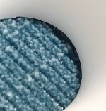
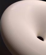
Something called LEDO 6060 Resin was apparently used. It's a fine surface to the touch with just of hint of coerce feeling like a 1000 grit sandpaper. Its really smooth at the throat but at the roundover one can feel a hint of the printed layers as a terass.
Upload path?
//
Upload path?
//
Attachments
Last edited:

That's probably the resolution of the STL file - too low for a SLA print.The circular lines are not camera moire but is there in reality.
Looks great. I think you couldn't hope for a better result with 3D printing.
Now I want to get mine ready ASAP, correct it and have it printed, but I must wait because too many obligations. Hard.
I remember you had the option to upload two different models/file formats. Which one was chosen. And was the material optional, i. e. the resin, or where there no options and this was defined by them?
I remember you had the option to upload two different models/file formats. Which one was chosen. And was the material optional, i. e. the resin, or where there no options and this was defined by them?
Wow, this size in SLA, 150 USD for both is a bargain. Super nice quality. The STL was exported at medium density setting from F360, since this is all that I ever needed for FDM. Maybe the high density would be even better.
Here is the data about the order:
3D file ST260Cutouts.stl
Dimensions 25.9×8.1×25.9 cm
Volume 311.16 cm³
Qty 2
Material LEDO 6060 Resin
Process SLA Color Natural white
Build Time 48 hours
One can see all the options by just upload a model to the jlcpcb site... quite a few; resins, color...
//
3D file ST260Cutouts.stl
Dimensions 25.9×8.1×25.9 cm
Volume 311.16 cm³
Qty 2
Material LEDO 6060 Resin
Process SLA Color Natural white
Build Time 48 hours
One can see all the options by just upload a model to the jlcpcb site... quite a few; resins, color...
//
Last edited:
I - finally - did measure my ST260 with a BMS 4538. Measurements at 1m and 100mW. Simulation 1m/2,83V targeted for use with an 10" driver I have somewhere....
Graphs represented with LMS software but measured with Clio 12.5´
TNT; can´t wait for yours as the 5530 has been on my list for a long time....


Graphs represented with LMS software but measured with Clio 12.5´
TNT; can´t wait for yours as the 5530 has been on my list for a long time....
I'm nor sure I will be able to produce all those angles..., but I trust the WG 🙂 I will do on axis SPL etc for sure.
How did you do the last "Simulated" one?
The 7k drop, whats the reason for that?
//
How did you do the last "Simulated" one?
The 7k drop, whats the reason for that?
//
Last edited:
I´m using LEAP5 for simulations. Done that for 20+ years. The dip is from the driver - don´t look at it, the normalized curves and DI tells more about the WG. But as the driver makes +20kHz nicely one can see that the WG is doing it`s job well 😉I'm nor sure I will be able to produce all those angles..., but I trust the WG 🙂 I will do on axis SPL etc for sure.
How did you do the last "Simulated" one?
The 7k drop, whats the reason for that?
//
Last edited:
Hi
The BMS driver, I believe, has two diaphragms. That's where they transition. I've seen this many times before.The 7k drop, whats the reason for that?
//
Nope, this is a single D simple one. Small with 38mm voice coil.Hi
The BMS driver, I believe, has two diaphragms. That's where they transition. I've seen this many times before.
Next iteration.

I wanted to have a slightly wider dispersion waveguide and have subsequently created a directivity error at the crossover point of 1.25k, as I kept the pattern width and it became wider at the low end.

Problem is, my compression driver cannot play an LR4 at 1k, it is dropping of too early. At 1k, it looks better:

I could not get the +XX/-XX pretext working with the renamer, so there was still plenty of typing.
I wanted to have a slightly wider dispersion waveguide and have subsequently created a directivity error at the crossover point of 1.25k, as I kept the pattern width and it became wider at the low end.
Problem is, my compression driver cannot play an LR4 at 1k, it is dropping of too early. At 1k, it looks better:
Ouch! That’s dedication 🙂 For next time: https://docs.microsoft.com/en-us/windows/powertoys/powerrename
I could not get the +XX/-XX pretext working with the renamer, so there was still plenty of typing.
If I would like to glue something to the WG (Material LEDO 6060 Resin), what would be a suitable product?
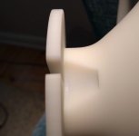
Also, now more closely inspecting the 2 WGs, I can see some small symmetrical deficiencies - if I place them back to back or front 2 front, there are glitches when observing the surfaces meeting, letting light thru. I doubt it will matter sonically.
//
Also, now more closely inspecting the 2 WGs, I can see some small symmetrical deficiencies - if I place them back to back or front 2 front, there are glitches when observing the surfaces meeting, letting light thru. I doubt it will matter sonically.
//
Another verification that both the OSSE contour and sumulations are very close to the truth.
38cm diameter OSSE printed in 1 piece and measured with Faital hf108ak
The impulses used are gated to about 3.5ms
If somebody knows how to get rid of the 1.8kHz pinch indirectivity - please share.
I've tried to vary every parameter with no success.
Raw with 200point smoothing and normalized to 0degree curve


Here are the contour plots of the simulation of the horn and the measurement both normalized at 0degree.


The horn was simulated freestanding with a rollback, and on the 3d print - the rollback is simply connected to the rest of the body (to make it printable)
It's about a kilo and a half of PLA


38cm diameter OSSE printed in 1 piece and measured with Faital hf108ak
The impulses used are gated to about 3.5ms
If somebody knows how to get rid of the 1.8kHz pinch indirectivity - please share.
I've tried to vary every parameter with no success.
Raw with 200point smoothing and normalized to 0degree curve
Here are the contour plots of the simulation of the horn and the measurement both normalized at 0degree.
The horn was simulated freestanding with a rollback, and on the 3d print - the rollback is simply connected to the rest of the body (to make it printable)
It's about a kilo and a half of PLA
It is hard to see from the pictures what the rollback/profile actually is but first thought is more gradual/bigger rollback might help on the 1.8k pinch. It looks similar to "main diffraction hump" on direct radiating driver although on 38cm baffle it would be octave lower than it is your measurments so might be something else 🙂 limacon working on with similar pinch on his thread, didn't post results yet.
I have had this “pinch” too, with a baffle mounted device. Working with the old OS-SE parameters, it did help to cut some of the termination with a lower factor Q. I am not sure what it does, but maybe it shifts the location where conical wall N transitions to super elliptical termination S on the wall area, without changing the profile in this area, while also reducing extension. However, the results only got as good after simulating a full enclosure, either because I had then used some more frequencies, or it has got something to do with diffraction around enclosure (or in your case only waveguide).
Thanks for the feedback.
Meanwhile here is some follow up on the ESP testing.
I finally made a new plug and horn using equal area input/output and tweaking slightly the exponent ratios.
The spikes are due to dips on axis.
I did a measurement with the plug as it was and then filed the plug entrance to "improve" the transition.
There was no difference in the measurements. As of now I no longer know what to suspect as the cause.
Here are normalized contour plots of the simulation (left) and measurement (right)


Raw measurements (with a bit of smoothing - 1000points)

The actual horn

Meanwhile here is some follow up on the ESP testing.
I finally made a new plug and horn using equal area input/output and tweaking slightly the exponent ratios.
The spikes are due to dips on axis.
I did a measurement with the plug as it was and then filed the plug entrance to "improve" the transition.
There was no difference in the measurements. As of now I no longer know what to suspect as the cause.
Here are normalized contour plots of the simulation (left) and measurement (right)
Raw measurements (with a bit of smoothing - 1000points)
The actual horn
- Home
- Loudspeakers
- Multi-Way
- Acoustic Horn Design – The Easy Way (Ath4)