Okay, but what stuck with my mind also was that he suggested a significantly wider patter for the tweeter above crossover, in order to have a smooth power response summation. When following his 1-1.2 lambda suggestion.I don't know but one of kimmo's suggestions is that the tweeter should have little to no on-axis baffle gain below the crossover.
Whoops, single chamfered is not nearly as good for higher frequencies. Is a double chamfer like 2 x 22.5 degree possible?- BTW, this is rounded vs chamfered (H, V, D), the last thing I wanted to implement for this release.
Excited! 🥳
With a fresh look at the elliptical waveguide, I also realized another reason: compared to a rectangular one, the area of the upper wall which is horizontal is lesser, due to its round transition. With a rectangular waveguide, the horizontal walls that are controlling the vertical response extend into the corners.How much of the size is given over to termination will have an effect on the smoothness vs polar control. You can see the negative effect of the loss of vertical directivity higher in frequency as the size and shape of the baffle become more significant.
I have been playing with the ROSSE formula and compared with the CE260 as a template:

Athough the profile is very close the DI and the impedance look rather different, it is very difficult to match the impedance with a decent performance.
But matching the DI is rather easy but yields a rather different profile:

Is that within expectation?
Here are some small WG to show what can be done:

smaller

smaller still:

I am looking at small devices because it is much more difficult to get them right so they provide better understanding of the limiting factors.
In addition and with the ROSSE formula it is straight forward to increase the radius and have a decent starting point for larger ones.
There is no target for the DI but rather general smoothness.
So far it seems that about 0.85 for the m parameter (apex relative position), about 0.28 for the r parameter (apex radius factor) and about 40deg for the coverage angle constitute a good starting point. With fixed driver exit angle, diamerter this leaves only 3 parameters to vary.
Any comment?
Athough the profile is very close the DI and the impedance look rather different, it is very difficult to match the impedance with a decent performance.
But matching the DI is rather easy but yields a rather different profile:
Is that within expectation?
Here are some small WG to show what can be done:
smaller
smaller still:
I am looking at small devices because it is much more difficult to get them right so they provide better understanding of the limiting factors.
In addition and with the ROSSE formula it is straight forward to increase the radius and have a decent starting point for larger ones.
There is no target for the DI but rather general smoothness.
So far it seems that about 0.85 for the m parameter (apex relative position), about 0.28 for the r parameter (apex radius factor) and about 40deg for the coverage angle constitute a good starting point. With fixed driver exit angle, diamerter this leaves only 3 parameters to vary.
Any comment?
Those are certainly interesting results of the optimization approach, depending on the quantity chosen as a target. I don't know if it's within expectation - those are all simply somewhat different profiles. Both DI and impedance are highly averaged quantities so some differences in the overall results are always to be expected.
Thanks for the effort, it's a nice thing to look at.
Thanks for the effort, it's a nice thing to look at.
Working on a new free standing WG (R-OSSE, ⌀570 x 257 mm, 1.4" throat).

Ath 4.8.2 released: http://www.at-horns.eu/#download
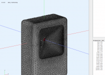
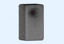
Adding enclosures described in User Guide, page 55: http://www.at-horns.eu/release/Ath-4.8.2-UserGuide.pdf#page=55
Adding enclosures described in User Guide, page 55: http://www.at-horns.eu/release/Ath-4.8.2-UserGuide.pdf#page=55
I tried this:
Ath (4.8.2) does something, but gmsh says the geo file contains a syntax error. The file stops halfway line 4435:
What am I doing wrong?
Code:
Throat.Diameter = 25.4
Throat.Angle = 10
Coverage.Angle = 45
Length = 60
Term.s = 1
Term.n = 4
OS.k = 1
Term.q = 0.98

Mesh.LengthSegments = 24
Mesh.AngularSegments = 64
Mesh.ThroatResolution = 4
Mesh.MouthResolution = 8 ; mesh element size for the horn outline
Mesh.SubdomainSlices = ; intentionally empty value (no subdomains)

Mesh.Enclosure = {
  Spacing = 30,30,30,200 ; edge distances (left,top,right,bottom) [mm]
  Depth = 200 ; enclosure depth [mm]
  EdgeRadius = 20 ; radius of the edge treatment [mm]
  EdgeType = 1 ; 1=rounded, 2=chamfered
  FrontResolution = 8,8,16,16 ; front side mesh element size (q1,q2,q3,q4) [mm]
  BackResolution = 20,20,20,20 ; back side mesh element size (q1,q2,q3,q4) [mm]
}
Ath (4.8.2) does something, but gmsh says the geo file contains a syntax error. The file stops halfway line 4435:
Code:
Line(2896) = {1448,14What am I doing wrong?
4.7.0 compiles my cfg ok. Sadly 4.8.2 errors out. I have not made any changes to the cfg. demo cfg's suffer the same.
Fixed! I had an lua54.dll in the ath4 folder. Seems to compile cfg's again now.
Info : Running 'C:\ath4\gmsh.exe mesh.geo -' [Gmsh 4.6.0, 1 node, max. 1 thread]
Info : Started on Wed Mar 30 23:48:56 2022
Info : Reading 'mesh.geo'...
Error : Unknown control point 1 in GEO curve 1
Error : Unknown control point 65 in GEO curve 1
Error : 'mesh.geo', line 1539 : Could not add line
Fixed! I had an lua54.dll in the ath4 folder. Seems to compile cfg's again now.
Last edited:
What additional lines are required to force an enclosure around an existing design? I've tried to enable Mesh.Enlcosure on the simple demos with no joy. Perhaps you could provide a demo12.cfg Thanks @mabat ! Such as this bare min cfg.
Throat.Profile = 1
Throat.Diameter = 25.4
Throat.Angle = 10
Coverage.Angle = 45
Length = 100
Morph.TargetShape = 1
Mesh.Enclosure = {
Depth = 200
}
ABEC.Polars:SPL = {
MapAngleRange = 0,180,37
}
Output.STL = 1
Output.ABECProject = 1
Last edited:
How is the "studio" situation any different?Honestly though, I don't see much need for cardioid in home situations unless they can work to lower the DI of the main source at its passband HFs. Otherwise any directivity factors get washed away below Schroeder.
What additional lines are required to force an enclosure around an existing design? I've tried to enable Mesh.Enlcosure on the simple demos with no joy. Perhaps you could provide a demo12.cfg Thanks @mabat ! Such as this bare min cfg.
In my case, it appeared after I had messed with ABEC.SimType. I had set it to 2, then to 1, then to 3 and 0, both of which do not exist, and then to 2 again. Don't know if there is a causal relation, also ran the ath command a couple of times. You will have in your ath command line print a line that indicates the enclosure was successfully meshed: -enclosure dimensions: 326 x 570 x 270 mm.
For half symmetry, you must add Mesh.Quadrants = 14, then you see the full enclosure. Otherwise, only quarter symmetry is inserted into ABEC. It then takes a while to calculate, so think first if you want to hit F5. sleepy
Thanks a thousand times @mabat!
Sleep now. Just managed to get this demo running.


Throat.Profile = 1
Throat.Diameter = 25.4
Throat.Angle = 10
Coverage.Angle = 45
Length = 100
Morph.TargetShape = 1
; -------------------------------------------------------
; Mesh Setting
; -------------------------------------------------------
Mesh.AngularSegments = 96
Mesh.LengthSegments = 60
Mesh.ThroatResolution = 5.0 ; [mm]
Mesh.InterfaceResolution = 7.0 ; [mm]
Mesh.InterfaceOffset = 5.0 ; [mm]
Mesh.ZMapPoints = 0.3,0.5,0.5,0.95
Mesh.SubdomainSlices =
Mesh.Quadrants = 14
Mesh.Enclosure = {
Spacing = 50,50,50,200
Depth = 200
EdgeRadius = 30
EdgeType = 1
FrontResolution = 8,8,16,16
BackResolution = 20,20,20,20
}
ABEC.SimType = 2
ABEC.Abscissa = 1 ; 1=log | 2=linear
ABEC.f1 = 200 ; [Hz]
ABEC.f2 = 16000 ; [Hz]
ABEC.MeshFrequency = 3000
ABEC.NumFrequencies = 19
ABEC.Polars:SPL = {
MapAngleRange = 0,180,37
Offset = 101
}
Output.STL = 1
Output.ABECProject = 1
Last edited:
Just wanted to set and leave it. Not any particular design. 3AM here. 🙂That's a very fine mesh, 3000? Only 19 frequencies, though, but you have them set to log, so the HF get their share.
At 97% now, doing some office duties in the meantime:
View attachment 1039914
Spectrum calculation
Number of data-sets 115
Observation script observation.txt
Frequency range 1,000kHz...20,000kHz, Abscissa = lin, NumFrequencies = 30
Threads used 12
ERRORS ------------------------
Number format problem in data block of import stream.
My observations process is complaining. I think I do not have sufficient CPU threads.
How do I set microphone level in observations.txt? The spectra that I get from VCAS do not look as intended:
Last edited:
Working on a new free standing WG (R-OSSE, ⌀570 x 257 mm, 1.4" throat).
would we be able to get the coeffs? 😀
Works fine but about 2h to complete on a 16/32 cores machine...
Results attached
Some projects that were fine with ATh4.70 are no longer working with Ath4.82
Is that expected?
Attachments
Last edited:
- Home
- Loudspeakers
- Multi-Way
- Acoustic Horn Design – The Easy Way (Ath4)
