Shouldnt the resistor be betwen 2 and 3 and take the signal off 2?Well, I am using that same circuit (although mine has filament bias) as you are, and I have built some with the black board from aliexpress that you have as well. What I'd suggest is to pull the opamps from their sockets, and stick a suitable resistor (sized for gain, maybe start with 1k) into pins 6 and 7. Connect one side of the resistor to output ground (pin 7) and one side (pin 6) to the grid stopper resistor on the 3a5 stage - you'll need to figure out how to bypass the volume potentiometer.
If you like it, you can tidy up the wiring and make it much neater.
With an anode follower(Thorsten Loesch) with ECC88 the gain may be small if the correct Riv is selected even with the use of CCS. That's why I went for tubes with higher gain like 6S4P and now 6HM5 which has three times higher gain than ECC88. To me the anode follower sounds much better than the SRPP as an IV, normally with both I used a cathode follower to keep the output impedance as low as possible and thus minimal impact of the next stage.Hi,
I gave the thermonic valve Loesch pdf above in a post but sorry do not remember the number of the post. If someone interested it is the revised version.
@Grunf, any input about a 6np23 but EV (low noise) version from 1973 to 1985 ? versus a nos ecc88?
If low noise as a E188CC what do you think about only one tube for both channels, i.e. just I/V a la Thorsten Loesch w/o grid stopper per the shematic he gave for the tda1541 (but with the good value for the R i/v of course) VS SRPP?
How much volts point did you choose for the 6np23 please ? 70V?
Do we really need a buffer with a high impedance pre/amp 25k input or more ?
If anyone please had gerbers for a gyrator and/ or colemann HV type reg it will be very appreciated 🙂
Why not SRPP for line driver writes in the conclusion of the article from valvewizard; What the SRPP is not an all-purpose line driver, because in such cases the load impedance could vary over a very wide range. A load impedance which is somewhat higher than the design value might not be too bad, but one which is lower would be disastrous. A cathode follower would be a much more sensible choice for this position.
To me the Ei ECC88 sounds better than the 6N23P (EV), quieter and better in the highs. It is a pity that there are no more to buy, but I have enough for my needs. 6N23P was at 90V.
Attachments

@Ryssen - my apologies, yes, you are correct. I found it easier to take it from the opamp socket and not take it from the AD1862, I think it was pin 11, but double check that!!Shouldnt the resistor be betwen 2 and 3 and take the signal off 2?
Missed these last few days of updates.
Impressive work @codyt on your IV stage.
Fran I'm loving your build into the old chassis. Nice! I'm always thinking of ways to use nice old chassis. Sometimes the psu or atleast the trafo may be useable.
I've finally finished the D1 IV. Powered it up. As usual the 25v AC trafo runs a little hot with over 30v unloaded. But hopefully the regs will take it. Powered it up to check and I have zero DC offset....and I mean dead steady zero. I'd expect something so maybe I have an issue but I guess i need to connect the signals up and see.
Thank you for sharing your experience.I'm glad to see tubes instead of op.amps, just keep going.
I used a similar scheme in my first DAC some fifteen years ago. Then I had two great mentors who were doctors for tubes in Croatia, unfortunately they are no longer with us today.
The first thing they objected to was the operating point ECC88 / 6N23P, with 1K in the cathode I ended up at 180R and a current over 10mA. This will be especially pronounced in SRPP junction without output buffer because SRPP itself is quite sensitive to the impedance of the next stage, in fact it should be calculated for a certain output impedance.
That's why I added an output buffer, simply cathode follower with ECC88. It was a big improvement. I played a bit with the tubes and in the end I chose the Ei ECC88 between 6N1P, 6N23P, Tesla PCC88 and Ei ECC88 which I still use today in the DAC in the output buffer.
For me, it was a big leap from op. amps and since then I haven't soldered a single op.amp on the signal path.
Finally, I enclose the scheme that I later used instead of SRPP, it is still a much better solution because you can go with a lower IV resistor and the sound itself was much better then SRPP.
I built your Tube Output Stage today and connected it to the AD1862. I'm happy to hear that I prefer the sound over the OP stage. The mid-range voice are especially attractive to me. Thank you.
I recorded it and uploaded it to YouTube. The soundtrack is streaming form Apple Music via airplay.
Hello, guys. I finished soldering the Dac. He looks very pretty! Now I have everything except PSU. I also solder a I2S pins (1,2,4,6) - is it correct? Also I buyed Amanero as transport. The connection between them is BCK-BCLK, LRCK-FSCLK, DATA-DATA, GND-GND - right?
I will take a photos at the start.
Does anyone compare a different frequences (44,1KHz, 96Khz, 192Khz) on the same music? - is there a difference between CD and Hi-Res?
I will take a photos at the start.
Does anyone compare a different frequences (44,1KHz, 96Khz, 192Khz) on the same music? - is there a difference between CD and Hi-Res?
Attachments
Congrats,
Yes the wirering is correct. Distance should not exceed around 10 cm and the shorter the better.
Well, from my experience you do not need high res cause most of the time the limitation is comming from the loudspeakers then the dac and its front end or output stage than can always be enhanced. For me high res is a lost of monney.
YMMV...I am sure some
I've tried various hi res sources, MQA and all that. I couldn't tell a big enough difference to warrant looking into it any further.
Today I got the D1 IV in on my 1862. Bit of a fiddle. It is kind of 'botched ' in there to test....aren't they all!
Well initial thoughts were good but maybe that is just my bias...I am always happy when things I've built even work, never mind sound good!
But yes it does sound very nice. Using the schematic as is, not altered the IV R for 1862 1mA. Plenty of output. Maybe sounds a little heavier in the LF than Patrick's IV. If this is to my liking or not remains to be seen...but initially I am liking it. I dont have the greatest repertoire to describe audible things.!
Although not related to this topic, but now I have seen these Nichicons for decoupling around AD1862. Yesterday my friend replaced them with OS-CON but around TDA1541, he listened to my advice and says the sound is much better now, more precise, cleaner, firmer bass, he is very satisfied. The regulators he uses are Salas shunts for +/- 5V and -15V.Hello, guys. I finished soldering the Dac. He looks very pretty! Now I have everything except PSU. I also solder a I2S pins (1,2,4,6) - is it correct? Also I buyed Amanero as transport. The connection between them is BCK-BCLK, LRCK-FSCLK, DATA-DATA, GND-GND - right?
I will take a photos at the start.
Does anyone compare a different frequences (44,1KHz, 96Khz, 192Khz) on the same music? - is there a difference between CD and Hi-Res?
Os cons definitely have their place. Digital is where I keep them but I am no expert.! Sorry for poor photo.
and further on the D1. I did no matching or setting up and as built it has negligible DC offset. I havent twiddled the trimmers. And I didn't fit the 10uF in the output cap chain.

and further on the D1. I did no matching or setting up and as built it has negligible DC offset. I havent twiddled the trimmers. And I didn't fit the 10uF in the output cap chain.
Hi,
OS CON were blue or violett plastic surrounding polymers from Panasonic. The actual are polymere aluminium cans: SEP, SEPC, SEPF etc. They kept the violett tough above the aluminium can...
They do not give the same result , dielectric has changed. The SEP is more advised than the others that are not easy to use, especially the SEPC...that often give not good results due to its lowish ESR and perhaps a difference inthe dielectric maybe.
The FP red serie above is a Nichicon iirc. But if it were me for 100 uF I would have chosen the United Chemicon 100 uF of the APSA serie...that are way better than the previous last time I benchmarked them as some others polymer brands. Though no needs to desolder the ones you populated.
Yes I apologise for generalising, realise that Os cons are a specific panasonic range. I sometimes wrongly use the term for hybrid polymers.
I have some blue/ally ones but I think they are kemet and not the APSA.
I have some blue/ally ones but I think they are kemet and not the APSA.
What kind of wires I should use for this connection?Distance should not exceed around 10 cm and the shorter the better.
I don't know these capacitors. Never use them. Maybe I change FG on Silmic 2 later...OS-CON
Guys, is there possibility to use a XLR connection and RCA (for convenience)? I mean a pseudo-balance connection for XLR cables. Is it difficult to implement?
But if they are in the decoupling reference position then it is better that there are electrolytes with low leakage current which os-con or other polymers certainly are not.Hi,
The FP red serie above is a Nichicon iirc. But if it were me for 100 uF I would have chosen the United Chemicon 100 uF of the APSA serie...that are way better than the previous last time I benchmarked them as some others polymer brands. Though no needs to desolder the ones you populated.
I don't know these capacitors. Never use them. Maybe I change FG on Silmic 2 later...
OS-CON for decoupling supply pins and UKZ for decoupling reference pins.
Os-con are with violett print
Attachments
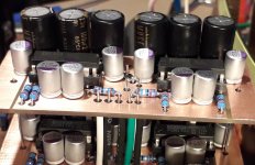
Interesting. I'll take note of that!Os-con are with violett print
Personnaly I do not like violett SEPC. Nore the UKZ that have odd and strange short bass, plus they are better if 100V. Anyway I would avoid both. But in the Grunf layout it maybe give some compensation that sounds good in the end withbthe others devices. You have to test to know. Be aware ad1862 and pcm1702 are very different animals as well.
- Home
- Source & Line
- Digital Line Level
- DAC AD1862: Almost THT, I2S input, NOS, R-2R