This is a thread about the Blomley amp. Hijacking it towards discussing/constructing another type of amp is thread jacking.
Not understanding what the Blomley concept is, is no excuse.
It is explicitly stated in the Rules that this is a no-no.
In such a case, it is good form to open a new thread and leave this for the original subject.
Jan
Not understanding what the Blomley concept is, is no excuse.
It is explicitly stated in the Rules that this is a no-no.
In such a case, it is good form to open a new thread and leave this for the original subject.
Jan
This is a thread about the Blomley amp. Hijacking it towards discussing/constructing another type of amp is thread jacking.
Not understanding what the Blomley concept is, is no excuse.
It is explicitly stated in the Rules that this is a no-no.
In such a case, it is good form to open a new thread and leave this for the original subject.
Jan
I'm still very confused and going to assume you're not replying to me as I have 100%, without a doubt, done nothing wrong. Are you saying @egra hijacked the thread or I did? If what I've done here is thread hijacking this forum can jump off a cliff for all I care. That's absurd.
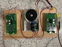
After some trial and error I finally got @egra's PCB working! I quickly assembled another so I could experience the Blomley circuit in stereo. I have to make some adjustments to the BOM on github due to a few minor conflicts; mostly with lead size (F1 and some resistors which were accidentally very large).
These are pictured with a +/-30V supply I had. I realize this is not ideal.
I was unable to make the capacitor modification previously suggested. I tried switching the 220uF to 470uF and could no longer adjust the quiescent current to get things working reliably. I can only assume @egra was referring to some other capacitor rather than Blomley's 250uF (C3 and C2). I'm not sure the bass response is suffering in my current assembly, however.
Once I was comfortable testing it out on my old garage sale Sony speakers (which, sounded pretty freaking great to me, actually) I moved this (very temporary and deadly) assembly into my living room project which is still under construction. I have yet to listen to this through a reasonable DAC and intend on doing that later this evening.
I'm now very interested in trying some other amp circuits and planning on buying a pair of one of the Neurochrome amps. If anything, this project has me really excited about amps.
On my todo list is to acquire a pair of Antek transformers. By my calculations the 100VA 22+22 will work with @egra's suggested bridge rectifier. The next step up is 200VA which would be major overkill unless I misunderstood.
The heat sinks I used are from amazon and branded "Easycargo" 150x69x36, US $16 for a pair. They seemed to drill and tap to M3 just fine. Soldering in Q14 and Q15 should be the very last step so you can get the distance to match the standoffs precisely (I learned this the hard way).
Attachments

In reply to the statement of a respected forum member :
The builds of Egra and Apson refer to an article by Dermot Herron already mentioned :
My 40-Year Love Affair with a Remarkable Amplifier—A Class B Amplifier for Audiophiles - Technical Articles
I am not in a position to argue it is Blomley, true Blomley or not Blomley.
My remark in post 115 was only in reply to post 111 here, which is clearly "no Blomley".
I suspect this schematic was intended to go somewhere else ! Astaro may want to explain.
I am not in a position to argue it is Blomley, true Blomley or not Blomley.
Jan mixed me up with Astaro (twice) and has failed to apologize or even acknowledge it. I will survive.
Egra's schematic is a "Blomley Class B Amplifier" because it is a direct reproduction of the schematic Blomley shared in the 1971 article. Saying otherwise is nothing short of disrespectful of Egra's time and contribution to this thread.
After some trial and error I finally got @egra's PCB working! I quickly assembled another so I could experience the Blomley circuit in stereo. I have to make some adjustments to the BOM on github due to a few minor conflicts; mostly with lead size (F1 and some resistors which were accidentally very large).
...
Once I was comfortable testing it out on my old garage sale Sony speakers (which, sounded pretty freaking great to me, actually) I moved this (very temporary and deadly) assembly into my living room project which is still under construction. I have yet to listen to this through a reasonable DAC and intend on doing that later this evening.
I'm now very interested in trying some other amp circuits and planning on buying a pair of one of the Neurochrome amps. If anything, this project has me really excited about amps.
Hey, great work! I still don't have all the parts yet, many are stuck in customs and some have yet to leave China and have been sitting ready for loading for over a month. Can't wait to hear these amps. My F3 PCBs just shipped too, so it's gonna be a busy time the next few months.
Rob
Last edited:
Jan mixed me up with Astaro (twice) and has failed to apologize or even acknowledge it. I will survive.
Egra's schematic is a "Blomley Class B Amplifier" because it is a direct reproduction of the schematic Blomley shared in the 1971 article. Saying otherwise is nothing short of disrespectful of Egra's time and contribution to this thread.
Yes I did mix you up, apologies.
Jan
The amplifier what I built (at least in terms of passive components) is exactly the same what Mr. Blomley published in1971. There was only one problem during the build, namely the choosing of right transistors. At that time, transistors had rather small hfe, so the choice fell on ZTX453/553. Maybe they have the smallest hfe. Otherwise, the circuit is rather tolerant to the transistors. The Blomley amp has a huge CLG, about 100dB, so with only 250mV input signal you can drive the output to clipping easely. The 250uF DC blocking capacitor in the feedback may be enough, but my 2-way closed box speakers give more bass if I increase the value of this capacitor. And again: my Blomley sounds noticeable better if I set the Iq from 20mA to 60mA.
What transistors and germanium diode did you use?
What transistors and germanium diode did you use?
Yes I did mix you up, apologies.
Jan
Thank you Jan I thought I had gone mad! I probably spent 10 minutes reading my posts because you had me wondering if I had indeed hijacked the thread! It would be one thing if you were nobody but you're JAN 🙂
The 250uF DC blocking capacitor in the feedback may be enough, but my 2-way closed box speakers give more bass if I increase the value of this capacitor. And again: my Blomley sounds noticeable better if I set the Iq from 20mA to 60mA.
What transistors and germanium diode did you use?
@egra thank you again for sharing your work -- this project has been a blast. Listening the other night I completely lost track of time and stayed up until 1:30 am. I used the ZTX453/553 along with some NTE184/185 pairs I found on ebay for Q1 and Q8 the NJW0302G/0281G on Q14 and Q15. The diode I got for D1 is supposedly NOS 1N34A I found on eBay. Another weird note: I had very weird/bad luck with the .39 ohm resistors from Digikey. Some were measuring as much as 22k despite being properly marked.
I just ordered my 22+22 100VA Antek transformers which I'm hoping will work out with the bridge rectifier you suggested earlier (GBU225KH). Unless my calculations are incorrect this should get me to ~60V. The next size up was 200VA and considerably more expensive but I hope I don't regret this.
I don't want to give too much of my subjective analysis at this point because I haven't plugged in a good DAC or my turntable (we have a 2 year old here and I have yet to find a safe zone for this amp in its current state).
I'm very interested in the subjective opinions others have had listening to this circuit -- maybe that IS for another thread. My first impression is that it doesn't do well with mixes containing artificially added distortion; the type an engineer might rely on to glue parts to a mix or make them more interesting, etc. It becomes very obvious; like the uncanny valley of audio. Compression attack and release times become obvious. It is my opinion that if you ever wanted a lesson in the "modern" mix engineer's bag of tricks and gimmicks you should start with this circuit. I cannot wait to hook up my turntable and put on some good pressings. Based on what I've experienced thus far I have a feeling it will be nothing short of traveling time.
I'm very interested in the subjective opinions others have had listening to this circuit -- maybe that IS for another thread. My first impression is that it doesn't do well with mixes containing artificially added distortion; the type an engineer might rely on to glue parts to a mix or make them more interesting, etc. It becomes very obvious; like the uncanny valley of audio. Compression attack and release times become obvious. It is my opinion that if you ever wanted a lesson in the "modern" mix engineer's bag of tricks and gimmicks you should start with this circuit. I cannot wait to hook up my turntable and put on some good pressings. Based on what I've experienced thus far I have a feeling it will be nothing short of traveling time.
That's a very telling statement. I judge an amp on its ability to reproduce such differences, as it's a basic requirement and shows that the amp's own character isn't masking the reproduction. While "noise shaping" for a pleasant sound has its place, I don't believe that place is in the reproduction chain.
In particular, "restored" B&W movies often have horrible sound channels, sounding like a cross between phasing, DBX expansion and noise gating. Frankly I'd rather hear some hiss and crackle than that horse puckey.
Just an update. I've listened to this thing like crazy now. Maybe 60 hours since my last post. I cannot go back to any other amp. I'm really looking for suggestions now as to what's better than this. It still makes me giggle, which it did AGAIN just now listening to an RL pressing of Led Zeppelin II that I have which inspired me to come on here and report. I think on Ramble On, in the left channel, someone is lightly tapping their fingers on a bongo or something; it was in the center of my room like I was listening in 5.1 or something.
My only complaint is that I can now pick out distortion on any input like crazy -- so I find myself favoring outside tracks on LPs similar to before I moved from elliptical cartridge to micro line...and I have a pretty nice turntable and cartridge now (Linn Sondek LP12 and Dynavector xx2 mkII) and didn't do this before with this setup.
My wife and I will sometimes sit for hours just listening to this amp. We're behind on every show we watch. This might sound stupid but I hope to at least some of you it will make sense.
It's not just vinyl. My vinyl rips are 96k and played back with a PCM5102A based DAC; not state of the art but that DAC has always been the most musical to me...and even that's incredible. Speaking of shows, the last time we watched a show I'd hooked the optical out of my TV to a inexpensive SMSL DAC (I believe an ESS implementation, not usually my thing but cheap at least) just for fun in order to hear Blomley's circuit in cinematic context -- it was season 3 episode 2 of Succession and we listened to the theme song 5 times, immediately stopped the show and listened to more records...
My friend keeps telling me I need to get an OLED TV. "When I start Netflix, it's just the Netflix logo hovering in the middle of a black space" he says -- that's exactly how I feel about this amp regarding music.
Put the spice down and build one of these.
I guess it's time to start building this puppy then. It will have to be pretty good to beat my Victor VFET though. 🙂
Been looking for an LG 3D OLED myself, at least they're immune from the usual flood lens detachment issue of the earlier models.
Been looking for an LG 3D OLED myself, at least they're immune from the usual flood lens detachment issue of the earlier models.
Nice work!Hi Mooly, All,
BTW that article by Dermot Herron includes a link to the EW/WW articles
http://www.keith-snook.info/wireles... to class-B Amplifier Design by P Blomley.pdf
<snip> ...."
I found this while looking at the Blomley circuit, I ran a few sims on it to find a good bias point, which I almost ordered PCB's for.
Those output MOSFET's are not the typical kind, but some exotic types specifically designed to have a linear(-ish) gain, whereas typical MOSFETs are designed to switch as fast as possible, with not much thought to linearity. Also in this setup the output FETS's untypically have gain, mostly you see voltage follower circuits, emitter or source. I can remember another design from way back in the 80's (?) in some electronics mag which also had MOSFETS output stage gain.
Maybe these transistors are similar to the Sony V-FETs?
I'm so glad someone else has had the same experience I had when I built the first of these for a friend (my own came later). I used to drive 300 miles to see my friend and to listen to his amplifier. They complained that you couldn't use it for background music - people stopped talking and listened! My experience too.Just an update. I've listened to this thing like crazy now. Maybe 60 hours since my last post. I cannot go back to any other amp. I'm really looking for suggestions now as to what's better than this. It still makes me giggle, which it did AGAIN just now listening to an RL pressing of Led Zeppelin II that I have which inspired me to come on here and report. I think on Ramble On, in the left channel, someone is lightly tapping their fingers on a bongo or something; it was in the center of my room like I was listening in 5.1 or something.
My only complaint is that I can now pick out distortion on any input like crazy -- so I find myself favoring outside tracks on LPs similar to before I moved from elliptical cartridge to micro line...and I have a pretty nice turntable and cartridge now (Linn Sondek LP12 and Dynavector xx2 mkII) and didn't do this before with this setup.
My wife and I will sometimes sit for hours just listening to this amp. We're behind on every show we watch. This might sound stupid but I hope to at least some of you it will make sense.
It's not just vinyl. My vinyl rips are 96k and played back with a PCM5102A based DAC; not state of the art but that DAC has always been the most musical to me...and even that's incredible. Speaking of shows, the last time we watched a show I'd hooked the optical out of my TV to a inexpensive SMSL DAC (I believe an ESS implementation, not usually my thing but cheap at least) just for fun in order to hear Blomley's circuit in cinematic context -- it was season 3 episode 2 of Succession and we listened to the theme song 5 times, immediately stopped the show and listened to more records...
My friend keeps telling me I need to get an OLED TV. "When I start Netflix, it's just the Netflix logo hovering in the middle of a black space" he says -- that's exactly how I feel about this amp regarding music.
Put the spice down and build one of these.
Some points of observation on some of the building some people have been doing.
1. This amplifier is very tolerant of transistor types. Provided the voltage and current rating are adequate, it will normally work.
2. The OA47 gold-bonded germanium diode is necessary (any gold-bonded germanium) but not a normal germanium diode.
3. The current-splitter transistors should definitely be fast-switching types with a very high ft. Signal transistors are not good enough.
4. I tried removing all AC feedback with a large capacitor to ground on the feedback path (the DC is necessary for stability) and crossover distortion was still invisible on the simulation output plot.
5. I tried a HI-FI integrated-circuit in a split-power-supply version and it sounded just like a normal amplifier, i.e inter-modulation distortion present. Has to be discrete transistors all the way, even in the pre-amp. Don't know why but any IC muddies the sound..
6. If you increase the rail voltage to 80 volts and choose adequate transistors you get a much higher power. Never needed it though - modern loudspeakers are quite efficient. But a pair of amplifiers in "push-pull" driven by a phase splitting transistor (equal resistors in emitter and collector) and driving the loudspeaker between the two amplifier outputs gives you huge power and clear sound.
7. Peter Blomley is an incredible designer - don't mess with his design - he knows more than you!
8. Vinyl is the best sound source by a long way. Digital 16-bit is very bad. One day I will try 24-bit digital media through a Blomley amp.
Dermot
(author of "My 40-year love affair with an extraordinary amplifier")
Member
Joined 2009
Paid Member
did I understand correctly - you are using these old Zetex transistors. This may be an important factor as they maybe the same kind that is used by Naim in their famous amplifier. These transistors have unusually high instrinsic capacitance and are 'credited' for helping the Naim amp achieve it's good sound. Perhaps you would also be interested in that amp as part of you hobby journey but it may not be any better than the Blomley for sound.
https://www.diyaudio.com/community/threads/tgm10-based-on-naim-by-julian-vereker.302454/
https://www.diyaudio.com/community/threads/tgm10-based-on-naim-by-julian-vereker.302454/
My 40+ years experience says "build the BJT Blomley JUST AS Peter Blomley designed and don't use ANY ICs anywhere including the preamp". The real 'presence' sound is instantly gone if you do.Nice work!
I found this while looking at the Blomley circuit, I ran a few sims on it to find a good bias point, which I almost ordered PCB's for.
Those output MOSFET's are not the typical kind, but some exotic types specifically designed to have a linear(-ish) gain, whereas typical MOSFETs are designed to switch as fast as possible, with not much thought to linearity. Also in this setup the output FETS's untypically have gain, mostly you see voltage follower circuits, emitter or source. I can remember another design from way back in the 80's (?) in some electronics mag which also had MOSFETS output stage gain.
Maybe these transistors are similar to the Sony V-FETs?
Once you hear it, you'll believe me. If you're not an instant total convert, you've made a mistake in the construction or choice of components or you've got an IC in the pre-amp.
The design is really robust and easy to build.
The Blomley is a design completely without measurable intermodulation distortion because it is nearly completely linear without feedback (well under 2% harmonic distortion WITH NO AC FEEDBACK). Compare that with normal Class B with >32% harmonic distortion with no feedback and Class A with >8% distortion. Intermodulation distortion happens in non-linear circuits only. As a test, in a simulation put a BIG (100uF) film capacitor (impractical in real life) in the small-signal side of the feedback components. Gain is enormous but you can make the input signal as small as you wish to get a non-clipping output. Then look at the output sine wave. It is perfect to the eye, without any crossover plateau. If you are clever, you can measure the distortion - I don't know enough about Spice. Then try the same with a normal Class B amp.
Peter Blomley made the gain of his amp arbitrarily 100. The more common gain is about 20 making clipping easier to control in modern setups. The ratio of the resistors in the feedback path can easily be changed.
This is the distortion of the original with the 47 ohm feedback return resistor reduced to 0.001 ohm. Distortion is remarkably low. The last image is the resistor back at 47 ohm. The open loop gain is around 82db.


0.6% distortion WITHOUT FEEDBACK! Much lower than I thought it would be. Lowest of all amplifiers I have ever heard of by a very long way. That's EXACTLY why it sounds so good and clear.
Leads to effectively NO intermod distortion and no transient intermod distortion (the momentary intermod distortion before the feedback has time to kick in (see my article)). And, in passing, no harmonic distortion with feedback on.
There still remains the feedback from the loudspeaker via R6 (Blomley original circuit) - I never worked out how to kill the AC - suppose you could just disconnect it since it is capacitor isolated anyway and has no DC in it. (This is also a brilliant piece of engineering because it reduces any distortion caused by a big electrolytic in the main path OUTSIDE the main feedback loop.) Please try it and see if it makes a big difference to the 0.6% THD ...
D
Well just for interest I tried with the classic 50w blameless Class B and that comes in at 1.75 thd.
The Blomley in the latest test comes in at 0.60 thd for 4 volts peak output into 8 ohm. Removing the 22k sees the output rise to 5.4 volts peak. Reducing the input so it comes back down to 4 volts sees thd rise to 0.74%
The Blomley in the latest test comes in at 0.60 thd for 4 volts peak output into 8 ohm. Removing the 22k sees the output rise to 5.4 volts peak. Reducing the input so it comes back down to 4 volts sees thd rise to 0.74%
- Home
- Amplifiers
- Solid State
- The Blomley Class B amplifier