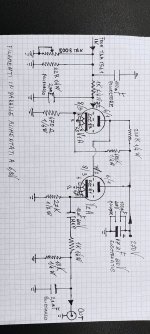
Hello! I would like to know your opinions on this output stage that I am attaching in the photo.
The only difference is that my current psu can only supply 230Vdc and not 270Vdc.
I must say that the sound result is amazing!
Any advice from you would be precious to me!
Granzie in advance.
Antonio.
The only difference is that my current psu can only supply 230Vdc and not 270Vdc.
I must say that the sound result is amazing!
Any advice from you would be precious to me!
Granzie in advance.
Antonio.
Attachments
What do you need advice about if you already know that it works and that you like the sound? Do you want to know how to modify it for a 230 V supply voltage?
This tube stage is certainly the best and the classic for the tda1541A. You surely can make it even simplier and better sounding with an ECC88 , I/V resistor'50R, no resistor for the grid stopper and no cathode follower (the ECC81). Reference for the tda1541A is Thorsten Loesch.
Try to find him threads here about the tda1541A and his tube stage. His paper for the diy community joined.
Hope that helps.
Try to find him threads here about the tda1541A and his tube stage. His paper for the diy community joined.
Hope that helps.
Attachments
IF you have a read of the valve wizard site for DC coupled cathode follower, its explained well.
http://www.valvewizard.co.uk/dccf.html
To adjust the operating point, you'll need to figure out the load line, and adjust the resistors to match.
http://www.valvewizard.co.uk/dccf.html
To adjust the operating point, you'll need to figure out the load line, and adjust the resistors to match.
For you and your guru perhaps. I find resistor i/v has no drive.This tube stage is certainly the best and the classic for the tda1541A.
If I calculated it properly, then reducing the 220 kohm resistor to 180 kohm and 680 kohm to 560 kohm should give you approximately the same bias point with 230 V supply as you have now with 270 V supply. The anode of the ECC83 should then end up somewhere around 80 V and its anode current around 0.85 mA.
Many thanks i will tri and i will let you knowIf I calculated it properly, then reducing the 220 kohm resistor to 180 kohm and 680 kohm to 560 kohm should give you approximately the same bias point with 230 V supply as you have now with 270 V supply. The anode of the ECC83 should then end up somewhere around 80 V and its anode current around 0.85 mA.
Thorsten Loesch is not MY guru but as one of the funder of AMR and Ifi should be good enough... and 50R is giving voltage enough with an ECC88 and is low enough to avoid too much distorsion with that chip. Of course if you know a better shematic, please share...and enligth us.For you and your guru perhaps. I find resistor i/v has no drive.
thanksThis tube stage is certainly the best and the classic for the tda1541A. You surely can make it even simplier and better sounding with an ECC88 , I/V resistor'50R, no resistor for the grid stopper and no cathode follower (the ECC81). Reference for the tda1541A is Thorsten Loesch.
Try to find him threads here about the tda1541A and his tube stage. His paper for the diy community joined.
Hope that helps.
I have to agree -2mADC offset is too convenient to ignore.
Use it to bias a tube which is happy to operate at near zero bias conditions.
Cathode connected to signal common, 10R maybe.
Grid to signal common 27 to 47R.
If you use a low Rp tube, you can remove the cathode follower.
My experience is that the AMR guy has this one right, and no doubt Zanden is the same.
It is an elegant solution which holds up under real world test conditions.
Last edited:
You would best served looking to someone else for a new flavour of TDA1541A kool aid. I haven't seen anything interesting with that thing since 1997.Of course if you know a better shematic, please share...and enligth us.
Then it doesn't matter that it doesn't work for me. Seems what is best for one isn't best for all.It is an elegant solution which holds up under real world test conditions.
Ah it was just a free non kool billet d'humeur ?You would best served looking to someone else for a new flavour of TDA1541A kool aid. I haven't seen anything interesting with that thing since 1997.
Oh I am certainly curious of your 1997 how to ? Oap 5532 ? discrete HDAM module from Marantz in a blind casing....Nah. However the post 2000 designs from Pedja Rogic you certainly call a guru as well are sounding very well without tubes.
As for the modern things, last time I tried a modern thing like a modern R2R discrete dac famous here...it sounded like a fry pan...
So the op should follow his way...though brand neww ecc81 an ecc83 is not the best way as the guy who made the tda1541 CD77 indicated here in diyaudio.

There is no best way just what one likes or doesn't like.So the op should follow his way...though brand neww ecc81 an ecc83 is not the best way as the guy who made the tda1541 CD77 indicated here in diyaudio.
First line of the opening thread - "Hello! I would like to know your opinions on this output stage that I am attaching in the photo."All the thread starter wanted to know is how to modify a circuit he is perfectly happy with for 230 V supply voltage.
Yep...as far you tried several to knowThere is no best way just what one likes or doesn't like.
- Home
- Source & Line
- Digital Source
- TDA1541 and others current out DAC tube out stage.