it would be nice and interesting if some expert could simulate the circuit on LTspice to be able to vary some components and understand what happens to the FFT, thd and gain. Obviously then I would be willing to measure these parameters to verify the correctness of the simulation.All the thread starter wanted to know is how to modify a circuit he is perfectly happy with for 230 V supply voltage.
They do not negate the opening post. Or back the "All" in your opening shot that was post 15.Please read posts #2 and #3.
Btw I re found for this thread very usefulls exchange around tda1541A and tubes.
https://www.diyaudio.com/community/threads/thorstens-tube-stage-for-tda1541a.197920/post-2735079
https://www.diyaudio.com/community/threads/thorstens-tube-stage-for-tda1541a.197920/post-2735079
But this,
Building the ultimate NOS DAC using TDA1541A,
must be the greatest. It is certainly the longest.Read it twice...it does not help that much for the ones that chose tubes though there are good passage about tubes and testimonials about members that tried tubes. John is more about silicon discrete I/V. Great thread that talk a lot about the digital front end as well...
Try to find radioman62 threads, there are some measurements about the ecc83 and ecc88 but also oaps and discretes I/V with the tda1541Ait would be nice and interesting if some expert could simulate the circuit on LTspice to be able to vary some components and understand what happens to the FFT, thd and gain. Obviously then I would be willing to measure these parameters to verify the correctness of the simulation.

It is elegant to use the -2mADC offset to bias a tube, rather than use Rk (with or without Ck) as per the OPs schematic.Then it doesn't matter that it doesn't work for me. Seems what is best for one isn't best for all.
There is a measurable impact on 'self-noise' (of the stage), and that it 'sounds better' was never mentioned.
Your subjective impression of 'resistor I/V' amounts to 'not much', and you are correct in that it 'does not matter', as it is both irrelevant and misplaced.
Last edited:
I can just as easily apply that to your pontification.as it is both irrelevant and misplaced.
Rfbrw, btw what the ref of tubes you used you was not happy with?
What is the 1997 alternative you liked best ? Any ref ?
What is the 1997 alternative you liked best ? Any ref ?
Even less of a fan of the TDA1541A than I am of resistor I/V but did see a virtual earth based valve I/V for it in Glass Audio I thought might worth building. BTW have a TDA1541A board from a 90's audio editor I once heard. Full of NE5534's. Sounded great. Must get it going. Can't have all that '5534 goodness lying around unused.Rfbrw, btw what the ref of tubes you used you was not happy with?
What is the 1997 alternative you liked best ? Any ref ?
Hello!
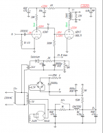
I proceeded to draw the diagram in a more decent way, in addition I also proceeded to measure some voltages (referred to GND) in some points and I also remember that the original power supply of the circuit was 270V, unfortunately my PSU can only supply 220V . Could any expert among you tell me if I have to or can I change something to make it work better?
Unfortunately I am not an expert on tubes.
Thank you!
Attachments
Don't know which parameter needs to be better but once you decide these two sites might help.
https://www.vtadiy.com/loadline-calculators/loadline-calculator/
http://www.normankoren.com/Audio/Tubemodspice_article.html
https://www.vtadiy.com/loadline-calculators/loadline-calculator/
http://www.normankoren.com/Audio/Tubemodspice_article.html
The input trimming potmeter is connected differently now, the 22 ohm has become 33 ohm and the supply voltage has changed.
Are you sure the potmeter connection is correct? You get a higher load impedance on the DAC output than with the circuit of post #1.
Are you sure the potmeter connection is correct? You get a higher load impedance on the DAC output than with the circuit of post #1.
Yes you have right, many thanksIn realtà sono abbastanza sicuro che la connessione potmeter del post n. 32 non sia ottimale. Il modo in cui è collegato nel post n. 1 è molto migliore.
Hello!If I calculated it properly, then reducing the 220 kohm resistor to 180 kohm and 680 kohm to 560 kohm should give you approximately the same bias point with 230 V supply as you have now with 270 V supply. The anode of the ECC83 should then end up somewhere around 80 V and its anode current around 0.85 mA.
Please can you read post #32 for measurement?
I don't understand the question anymore since I saw post #32.
I thought you had this circuit running on 270 V and wanted to know how to modify it for 230 V, but now 230 V has become 220 V and you apparently already have it running on that lower supply. Hence I only commented on the suboptimal potmeter connection.
I thought you had this circuit running on 270 V and wanted to know how to modify it for 230 V, but now 230 V has become 220 V and you apparently already have it running on that lower supply. Hence I only commented on the suboptimal potmeter connection.
The real condition is that of post # 32, except for the input trimmer.I don't understand the question anymore since I saw post #32.
I thought you had this circuit running on 270 V and wanted to know how to modify it for 230 V, but now 230 V has become 220 V and you apparently already have it running on that lower supply. Hence I only commented on the suboptimal potmeter connection.
Now my question is if I have to modify R3-4-5-6 because they continue to have values for a PSU of 270V, and instead I am have a PSU of only 220V.
Also I would like to know if I can decrease the value of C5 as well.
Thanks in advance if you want / can help me.
Antonio
Apparently your ECC83 is a bit weaker than the curves in the Philips datasheet http://www.r-type.org/pdfs/ecc83.pdf indicate, but not dramatically so. You may have a bit of grid current due to the relatively small negative grid voltage (the grid must be somewhere around -0.06 V while the cathode is at +0.44 V, so the grid-cathode voltage is about -0.5 V). Then again, you drive it from a quite low impedance and the current is limited, so it shouldn't do any harm. I wouldn't touch it if it sounds good.
Regarding C5, is there any reason why R8 needs to be so low? You can reduce C5, but how much depends on how much loss you are willing to accept at the bottom of the audio band and on R7 + (R8 in parallel with whatever is connected to out).
Regarding C5, is there any reason why R8 needs to be so low? You can reduce C5, but how much depends on how much loss you are willing to accept at the bottom of the audio band and on R7 + (R8 in parallel with whatever is connected to out).
- Home
- Source & Line
- Digital Source
- TDA1541 and others current out DAC tube out stage.