Thanks for your answer, in any case what are the correct voltage values that would be better to obtain in the points measured by me?Apparently your ECC83 is a bit weaker than the curves in the Philips datasheet http://www.r-type.org/pdfs/ecc83.pdf indicate, but not dramatically so. You may have a bit of grid current due to the relatively small negative grid voltage (the grid must be somewhere around -0.06 V while the cathode is at +0.44 V, so the grid-cathode voltage is about -0.5 V). Then again, you drive it from a quite low impedance and the current is limited, so it shouldn't do any harm. I wouldn't touch it if it sounds good.
Regarding C5, is there any reason why R8 needs to be so low? You can reduce C5, but how much depends on how much loss you are willing to accept at the bottom of the audio band and on R7 + (R8 in parallel with whatever is connected to out).
And above all .... what is R4 for?
As for R8 instead I think I could easily replace it and I imagine that also, empirically if I bring it to 100k, maybe I could decrease C5 to 1uF or something like that.
One would usually use a more negative grid bias voltage, but I think it would do more harm than good in this case. Assuming that the heater supply of the ECC81 is grounded, you can't make the ECC83's anode voltage much higher than it already is. At low anode voltages, the ECC83 works in a much straighter part of the IA versus VG curve at -0.5 V than at -1 V...-1.3 V.
Attachments
Maybe not the best settings and komponent value selection for the ECC83 gain stage. tipically 220K at anode load is simply tooooo much.Hello! I would like to know your opinions on this output stage that I am attaching in the photo.
The only difference is that my current psu can only supply 230Vdc and not 270Vdc.
I must say that the sound result is amazing!
Any advice from you would be precious to me!
Granzie in advance.
Antonio.
Making the load line almost flat and more important "eating" voltage for ECC83. Makinf the Anode voltage of ECC83 too low.
220K load for ecc83 is typical for guitar amlifiers and PA tube gear...
I dont see tha point of using ECC81 in the buffer stage since tha output resistance is app. 1/Transconductance. And the Transconductance of ECC81 is not high but opposite - low. In that place better suited is 5687 tube or other with higher S
.
I will try to sketch an example
If someone prefer less Output voltage p-p just decrease Riv value from 22 ohm to 11 for the 2.4V p-p. 5687 can run even with bit more Ia and in that case decrease Rcurrent value from 27K to 25K or 24K but not more than 12mA for 5687. There is no point to fo more with current, nothing changes but 5687 coming closer to the power limit...
.
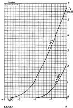
ECC83 is set like Neumann style battery biasing. 1.2/1.25V is the most linear region. with Ia=3mA and Ua=265V Pa is at 80% of max.
So the tube is operating in real tube voltage. At least tubes are voltage devices 🙂. The Load of ECC83 is 68K and it is pefectly enough for the amplification. Load line have a slope, and not tend to be parallel with X axess...
.
NiCd or NiMh or other smaller battery could be used but not from high mA/h. Goal is to emulate trickle charge current of about 40 x Ia and that is 120mA so the standard close value is 150mA/h
.
Optional alternative biasing circuit RC classic type is from very close low end of BW with very smal phase shift in low Fo
Distotion are minimum and almost without 3rd-H...
.
This is important: The circuit nas NO HF filtering, so that could be added
Hi Zoran, unfortunately I do not know how to move in the world of tubes, and therefore I still cannot understand and know what are the adjustments to make the best use of this circuit powered at 220V instead of 270V, Also I have not yet understood what R4 is for and if I have to also change its value. Of one thing I am sure of, however, and that is that this output stage sounds damn good for my taste and allows you to try out different ecc83s and ecc81s until you find the right mix that will delight your ears.Maybe not the best settings and komponent value selection for the ECC83 gain stage. tipically 220K at anode load is simply tooooo much.
Making the load line almost flat and more important "eating" voltage for ECC83. Makinf the Anode voltage of ECC83 too low.
220K load for ecc83 is typical for guitar amlifiers and PA tube gear...
I dont see tha point of using ECC81 in the buffer stage since tha output resistance is app. 1/Transconductance. And the Transconductance of ECC81 is not high but opposite - low. In that place better suited is 5687 tube or other with higher S
.
I will try to sketch an example
So I ask you if you can / want to help me simulate this circuit as you have already shown you know how to do in the next post, so that you can understand what and where to modify to better optimize.
Thanks in advance
Antonio
Hi Antonio If You are satisfied you dont have to move from circuit alrady in use. I just make some comments from my experience with tubes. I simply count more when the tube working in higher Ua if the linear region follow this, then with kower almost solid state value of Ua... Same is from personal tryout for huge RLoad, and reasonable load connected with tube anode charackteristis. Soud is a big difference. Regardless of brand type of the tubes.
At least chsnge value of 10K at the output. It is not final loading resistor. The one in in the next stage IS. Output C is for 10K load But if Yu have 10K in nex stage and this 10K at the output, that will be parallel value of 5K and 10uF would not be enough for good low end... Other thing is that tis 5K will heavily loading buffer that wil go into effect of compession... So by this "little" things I can tell how is the global sound... So this resistor is OK to be in place BUT 1meg or 2.2meg value, Just to terminate output not to additionally load buffer.
At least chsnge value of 10K at the output. It is not final loading resistor. The one in in the next stage IS. Output C is for 10K load But if Yu have 10K in nex stage and this 10K at the output, that will be parallel value of 5K and 10uF would not be enough for good low end... Other thing is that tis 5K will heavily loading buffer that wil go into effect of compession... So by this "little" things I can tell how is the global sound... So this resistor is OK to be in place BUT 1meg or 2.2meg value, Just to terminate output not to additionally load buffer.
Ok ..but not yet understood what R4 is forHi Antonio If You are satisfied you dont have to move from circuit alrady in use. I just make some comments from my experience with tubes. I simply count more when the tube working in higher Ua if the linear region follow this, then with kower almost solid state value of Ua... Same is from personal tryout for huge RLoad, and reasonable load connected with tube anode charackteristis. Soud is a big difference. Regardless of brand type of the tubes.
At least chsnge value of 10K at the output. It is not final loading resistor. The one in in the next stage IS. Output C is for 10K load But if Yu have 10K in nex stage and this 10K at the output, that will be parallel value of 5K and 10uF would not be enough for good low end... Other thing is that tis 5K will heavily loading buffer that wil go into effect of compession... So by this "little" things I can tell how is the global sound... So this resistor is OK to be in place BUT 1meg or 2.2meg value, Just to terminate output not to additionally load buffer.
HereR4 da quale sch?
Attachments
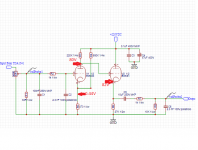
R$ and R5 are forming circuit for +0.4V biasing for unput tube. That is actualy negative Ug because G is in 0 potentional.Here
Taht can be done wirhout the R4 but value if the R5 coud not be tha same...
Also maybe R4 with R5 creating a shunt resistance from Power supply to ground. From my experience any shunt in tube circuits for small signal can little "damage" sound. Any even one resistors for bleeding the power caps.
.
But that is not the main "problem" of this circuit. Simply the Va is too much low = +79.56V.
I will repeat tube is the voltage device not the current device.
.
Second "problem" is too high Rload of 220K. There are no need for that kind of amplification, AND the load line is tend to be parallel with X axess.
The cd77 from amr is a first stage 6072A then a 5687.
There is also the one with the ecc88 alone talked by T Loesch in the link I gave page 2...and also cheap tube alternative.
As a noob with tubes I chose to follow the ec88 with the help of a mate, expensive choke plate swaped for a hybrid mu follower aka Moglia gyrator.
Proven design that work well with the tda 1541.
good morning and best wishes for a happy Easter to all.R$ and R5 are forming circuit for +0.4V biasing for unput tube. That is actualy negative Ug because G is in 0 potentional.
Taht can be done wirhout the R4 but value if the R5 coud not be tha same...
Also maybe R4 with R5 creating a shunt resistance from Power supply to ground. From my experience any shunt in tube circuits for small signal can little "damage" sound. Any even one resistors for bleeding the power caps.
.
But that is not the main "problem" of this circuit. Simply the Va is too much low = +79.56V.
I will repeat tube is the voltage device not the current device.
.
Second "problem" is too high Rload of 220K. There are no need for that kind of amplification, AND the load line is tend to be parallel with X axess.
so in concrete, what are the reference voltages that I should try to obtain so that the circuit can work at best with 220V of psu?
This is the version of 12AY7 tube - ecellent and very good for this purpose. With slight less amplification could be set to the linear region of operqtion with minimum distortion.6072A
Classic tube design, closed box anode, mediom transconductance etc in one word real tube
ECC88 is totly opposite - open anode, high transconductance 90V is max Ua in one word closer to the mos fet then to the tube 🙁
And the sound follows
(But only my individual opp.)
E188CC not a real tube for that purpose ? I have one from Herleen 1974... I think he made the Thermionic valve article for noobs as I, story to try tube, yet simple but sounds good.
I know nothing with tubes. Seems Thorsten knew what he made with the 6072A fornthe first I/V stage (at the risk of a higher resistor, he said up to 60/70 R is ok with all the samples of tda1541 he measured... Philips datasheet was a little conservative)...the buffer is the good sounding 5686 GE1Jan version (blue marking ?)
I know nothing with tubes. Seems Thorsten knew what he made with the 6072A fornthe first I/V stage (at the risk of a higher resistor, he said up to 60/70 R is ok with all the samples of tda1541 he measured... Philips datasheet was a little conservative)...the buffer is the good sounding 5686 GE1Jan version (blue marking ?)
Last edited:
Well with a 44 Mu the 6072A is indeed better than the ECC88...
Is a high transconductance not whished for I/V dac stage ?
Is a high transconductance not whished for I/V dac stage ?
Internal configuration of 6072A and ECC88 is totally different one have open anode other closed. And main difference in datas is Anode voltage limit. ECC88 is just about 90V that is hardly can considered like high voltage... 🙁Well with a 44 Mu the 6072A is indeed better than the ECC88...
Is a high transconductance not whished for I/V dac stage ?
.
In Riv concept, when Iout dac are converting current to voltage directly at Riv, with opposite phase voltage result, trans-conductance have no impact. The following tube stage is just amplifier of that little voltage, and with amplification doing another phase shift 180deg, setting the right phase for the buffer (buffer does not have phase shift as well as not giving amplification, just lowering output impedance of the final device output...)
The phase in the Riv configurations are impotrant. Because a lot of designs are confused with that.
When Io from dac coming to the Riv we have positive phase current to negative phase voltage conversion.
But if we just invert digital data line at the input of DAC, the Iout wil have negative phase and after Riv we will have positive, right phase voltage output.
.
Single tube amplification stage turning tha amplified voltage to 180deg phase shift.
I am talking about this because every tube premplifier (without input or output transformer) turning the phase in opposite than at the input.
And amplifier, as mostlu phase in=phase out will drive the speakers in opposite phase... 🙁
.
(Just one remark, the clessic OP amp trans-impedance stage, like we have in most comertial devices, does not doing the phase shift output.)
first the phase shift of 360deg is actually no shift. 0deg=360deg full circle...
.
SRPP or mu follower, as amplification stages, resulting 180deg phase shift. 0deg input = 180deg out, +Vin =-Vout or -Vin =+Vout
.
SRPP or mu follower, as amplification stages, resulting 180deg phase shift. 0deg input = 180deg out, +Vin =-Vout or -Vin =+Vout
Last edited:
- Home
- Source & Line
- Digital Source
- TDA1541 and others current out DAC tube out stage.