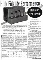
It doesn’t, it is nowhere near what I’ve shown in the first post. How do I know? Because that’s one of the 1st designs I prototyped just to have a baseline.Looks a lot like a Mullard 5-20, a bullet proof design with a good record.
So what is the problem? Just build & expect good results. And enjoy.
Thanks! Yes, I am aware of that, on the prototype the right 22K anode resistor actually has a 5K trimmer in series which is used to make sure both outputs match to within a few mV.Don't think this is the problem but this shows the AC imbalance with such a setup.
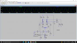
Anyway you wanted i dotting and t crossing. Still don't know why the distortion suddenly increases. You would expect it move with bias as class B will be later.
Thanks! I tried that, and without the large tail resistor distortion is at least a factor 4x worse. My take on this is that the distortion profile of the LTP set up in the way I have it configured must be the inverse of the output section as when the global loop closes they, partially, cancel out.This would be my version with a bit more swing.
You are correct in saying that the rounding of the peaks of the waveform in the LTP actually does compensate for the distortion in the output stage. Sort of distortion cancellation. In fact if you look at the drive to the output devices you will find the NFB has rounded the drive waveforms. However I am not sure such distortion cancellation can be relayed upon and in my view its better to design linear. I don't know if 43% UL may be a bit high.
I think when I looked at this before two 6550's in parallel at 430V was more linear than a KT88 at 530V.
Yes, please look at the measurements with the different current settings for the KT88s I posted earlier, you’d expect the point where the amplifier enters class-B to move with the current setting (i.e. lower current it shifts to the left, higher current shifts to the right). The fact that it doesn’t and the point where the distortion starts to increase is the same for all, hence the cause for this lays elsewhere.Anyway you wanted i dotting and t crossing. Still don't know why the distortion suddenly increases. You would expect it move with bias as class B will be later.
My take on what causes this is that the LTP runs out of headroom, which I plan to test tomorrow by providing it with a higher supply voltage, to see if this point moves.
Proto 30 is definitely the basic Mullard 5-20, of which there are many iterations since its introduction in 1956.It doesn’t, it is nowhere near what I’ve shown in the first post. How do I know? Because that’s one of the 1st designs I prototyped just to have a baseline.
66 yrs ago. Shew us where your cct Proto 30 is significantly different. I'm curious.
Attachments
Yes rounding to tops of the waveform with the LTP plate voltage could easily lead to early clipping - but still don't think that's it. Your not overloading the distortion measurment.
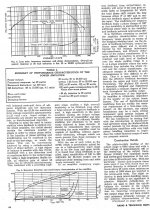
Look at the THD vs. output power measurement I included, now show me a Mullard 5-20 design that does the same or better. They don’t, I looked at them in great detail in the simulator and have built a few variations to get a handle on what they’re capable of and they don’t offer this level of THD performance. But am welcome to try any suggestions you might have as you have far more experience than I do, I’m just a nitpicking perfectionist that bites down on something and won’t let go until I have extracted every last bit of performance from it.Proto 30 is definitely the basic Mullard 5-20, of which there are many iterations since its introduction in 1956.
66 yrs ago. Shew us where your cct Proto 30 is significantly different. I'm curious.
If you fancy pre-distorting the signal look at this sort of thing
https://www.tubecad.com/2006/05/blog0066.htm
https://www.tubecad.com/2006/05/blog0066.htm
Yes, I’m not sure yet either, would love to hear your thoughts though, and/or try to get a handle on the mechanism at play here if you have suggestions for things to try?Yes rounding to tops of the waveform with the LTP plate voltage could easily lead to early clipping - but still don't think that's it. Your not overloading the distortion measurment.
On that note, one thing that puzzled me is that decoupling the 10R kathode resistors for the KT88s reduced distortion across the board. I didn’t expect that as effectively, without the decoupling, they see a little local feedback so the net distortion for the output stage should be lower without decoupling. So there’s certainly a distortion cancellation mechanism at play here, which, consequently, only shows with a 6922 (any brand, I tried EH, JJ and NOS), substitute for a ECC82/ECC99 and the distortion is much, much higher.If you fancy pre-distorting the signal look at this sort of thing
https://www.tubecad.com/2006/05/blog0066.htm
Nothing I’ve tried thusfar seems to, I plan on increasing the supply voltage to the LTP in 20V increments tomorrow to see what that does.I think I would ask - does anything move that nee point.
Yes I think you've got some distortion cancellation taking place. It will be more obvious with the NFB disconnected.
Marginally, repeating the same THD vs. output power measurement at 100Hz shows pretty much the same result, at 10kHz the knee starts earlier but that’s mostly due to the fact THD at 10kHz is higher to begin with.Does it shift with frequency?
P.s. if I swap the OPT for any of the others (similar specs.) I have I basically get the same result, which tells me the OPT is not a contributing factor in all this, or at least not specific to one type/model.I think I would ask - does anything move that nee point.
- Home
- Amplifiers
- Tubes / Valves
- KT88 PP - Dotting the Is, crossing the Ts