Hi Randy, great, many thanks for the explanation.
Just a short question to "pots vs. fixed resistors": what are the pros and cons?
Is the version with pots "better" in terms of sound quality or reliability/safety or is it just nice to have?
Because I don't have the dummy loads and the signal generator (okay, CD would work too).
If I choose to go with pots, would an 8R 200w dummy load work?
Last edited:
What about using FQA28N15 instead of the good old IRFP240? FQA's are in stock at Mouser and are showing good specs...
@PlottHi Randy, great, many thanks for the explanation.
Just a short question to "pots vs. fixed resistors": what are the pros and cons?
Is the version with pots "better" in terms of sound quality or reliability/safety or is it just nice to have?
Because I don't have the dummy loads and the signal generator (okay, CD would work too).
If I choose to go with pots, would an 8R 200w dummy load work?
Pots allow for flexibility in design, especially when you don't have full control on what size heatsink, how closely matched the transistors are, etc...the diyer is using. The only risk is that the value can vary over time although I have not experienced that as I use standard issue, good quality Bourns pots. The quality of the resistive element in most of these pots is not going to be as low noise, etc...as a typical resistor, so it becomes a subjective debate at that point. Once you have finalized your build and set P1, P2, P3, you can substitute for the near equivalent value fixed resistor (which may or may not be available at that EXACT value). Anyway, Randall's PCB design has tremendous flexibility built into it to allow for experimentation and flavoring which is what diyaudio is all about.
An 8R/200W dummy load is overkill but would totally work when setting the AC current gain . I am using an 8R/100W load from Parts Express.
Best,
Anand.

It looks like a nice part and I certainly don't see an issue with using them.What about using FQA28N15 instead of the good old IRFP240? FQA's are in stock at Mouser and are showing good specs...
I think the Fairchild/Onsemi's come in rails of 30 so for matching purpose I would suggest buying in multiples of full rail.
Also, it's a TO3P part which uses M3 mounting screws. I had to enlarge the mounting holes on some Fairchild mosfets
because I wanted to use them with heatsinks that had been previously tapped for 6-32 screws.
Hopefully others can chime in.
Hi Anand,
many thanks - so I could use the amp with the preset pots without adjustments too (preset pot plus resistor is the original Aleph 60 fixed resistor value) and could play with it later.
Cheers!
many thanks - so I could use the amp with the preset pots without adjustments too (preset pot plus resistor is the original Aleph 60 fixed resistor value) and could play with it later.
Cheers!
Anand nailed it. Pots are there for experimenting and adjusting. If you go with the fixed resistors in the original schematic (and jumper the pot on the pcb!) you’ll get a fanatastic sounding amp.
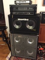
the big dummy load is for a project that I have in the works for a friend. Ampeg SVT clone with additional gain stages in the preamp section. It will shake my house.
the big dummy load is for a project that I have in the works for a friend. Ampeg SVT clone with additional gain stages in the preamp section. It will shake my house.
@Plott: Anand and Randy have covered the salient points. Just remember that legions of Aleph builders from years past built theirs without any pot adjustments and if you choose to go with fixed resistors, it'll still be perfectly fine.
BTW, assuming the power mosfets and source resistors are fairly well-matched, you can also see the effect of the AC current gain by playing a sine wave into a load and just compare the AC voltage measurements across a source resistor for the gain devices ('lower half) vs one from the current source ('upper half'). If they're equal then you are at 50% AC gain.
BTW, assuming the power mosfets and source resistors are fairly well-matched, you can also see the effect of the AC current gain by playing a sine wave into a load and just compare the AC voltage measurements across a source resistor for the gain devices ('lower half) vs one from the current source ('upper half'). If they're equal then you are at 50% AC gain.
Begging the indulgence of the other kind readers..the big dummy load is for a project that I have in the works for a friend. Ampeg SVT clone with additional gain stages in the preamp section. It will shake my house.
SVT already stands for "Wretched Excess," and yet I have to admire the desire to pile on a little bit more.
My own solution to this issue of not enough tubes was to build a separate tube hybrid preamp with an outboard PSU. Five 9-pin tubes, a pair of high-voltage Mosfet followers and three signal transformers made two separate channels that could be optionally combined in either sequence, plus a final White Cathode Follower if extra drive was necessary. Too much fun.
Attachments
That is fantastic! I'll DM you on the preamp, I want to know more!Begging the indulgence of the other kind readers..
SVT already stands for "Wretched Excess," and yet I have to admire the desire to pile on a little bit more.
My own solution to this issue of not enough tubes was to build a separate tube hybrid preamp with an outboard PSU. Five 9-pin tubes, a pair of high-voltage Mosfet followers and three signal transformers made two separate channels that could be optionally combined in either sequence, plus a final White Cathode Follower if extra drive was necessary. Too much fun.
My plan is to mock up the following: Carvin X100B pre into SVT pre into a 500W Icepower amp. I have the donut and an old PA chassis to do the mockup in. I need to finalize schematic and get building. It's in line after many other build projects, though.
If the magic is in the preamp sections I'll avoid a whole lot of weight for the power amp section. The end goal is a 1 box setup to replace my buddy's live music setup with 2 heads. If I can take >100 pounds in one heavy and one extremely heavy box down to 1 lighter box that sounds as good, it's a win. I have a SVT3 Pro for testing / reference. His loaner 70's SVT is back at his home or practice space.
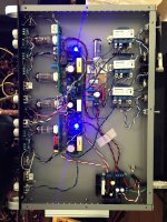
Some porn, now waiting for the Anteks and chassis.

Thank you!Nice, where did you buy those 3w resistors?
They are from Digi...
Are those Gareth Robert designed?
Sorry for my ignorance, who is Gareth Robert? 🤔Are those Gareth Robert designed?
Randy, in your build you don't use the rectifier/snubber and CL-60 boards (I don't see the boards at least).
Are this boards a must or just nice to have?
I don't have Quasimodo, so determining the snubber resistor is not possible.
Are this boards a must or just nice to have?
I don't have Quasimodo, so determining the snubber resistor is not possible.
Are those Gareth Robert designed
He designs PCBs based on pass lab designs, they look like a similar style.Sorry for my ignorance, who is Gareth Robert? 🤔
Where did you purchase the boards?
The designer was Randy (rhthatcher here at DiyAudio), and it was a group buy here.He designs PCBs based on pass lab designs, they look like a similar style.
Where did you purchase the boards?
I think the GB is closed now.
Are those Gareth Robert designed?
I did these boards. There is a Group Buy #2 open now if you're interested.
https://www.diyaudio.com/community/...fier-for-modern-ums-chassis-group-buy.379734/
Randy, it´s me again 🙂
The circuit diagram shows, that the emitter of Q4 goes to the negative rail - but on the pcb this pin is marked with C for collector. The shape of Q4 on the board gives the right position, we should ignore C and E because they are reversed. The same applies for Q5, the collector goes to CSG, but on the pcb this pin is described with E for emitter. Again, the shape of Q5 on the board shows the right position.
And now, I go de-solder and re-solder 😀
- Home
- Amplifiers
- Pass Labs
- Classic Aleph Amplifier for Modern UMS Chassis Builder's Thread