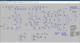
Alright, the subject is pretty self explanatory, I'm at that stage of a design where I'm dotting the i's and crossing the t's. Below is the schematic which represents the status quo of the current prototype with an actual measurement of THD v.s. output power at 1kHz included. I've obviously tried just about every trick in the book, hence the fact this is the 30th revision of the prototype schematics, some revisions were small just a resistor value change, some larger, and I am hoping to get some suggestions on how to improve THD > 20W, as currently the THD rises significantly after that point. I have the prototype on the bench, and the simulation running on the PC and interested to try suggestions, as I'm sure there's still room for improvement! Looking forward to your replies!
Attachments

40%, just your regular old UL transformer, nothing special really.Sorry what percentage UL?
Ok then because the transformer windings are tightly coupled then L1 = L2 = (.40/2)^2*La and L4 = L5 = (.60/2)^2*La where La is the total primary inductance.
Oh wait, I should've mentioned that, don't mind the transformer values in the LTspice schematic, those are anything but accurate.
Why is that? Both on the bench and in the simulator I see exemplary performance with the anodes being within a few 10s of mV of each other, unless you know something I don't?The LTP phasesplitter is inherently unbalanced as shown.
I think to analyze distortion you need a reasonably accurate match of the transformer - in particular the UL % position. I would also expect that without a CCS in the LTP tail the anode AC voltage swings would be different causing 2nd harmonic distortion. You can get round this by making the plate resistors non equal which will get the AC right and the DC wrong.
I tried a CCS and a rather elaborate CCS for the LTP, but all of these attempts resulted in worse THD results, even with the operating conditions of the 6922 being exactly the same. What I haven't tried yet I now realize is a CCS with a series resistor on top, not sure whether that would make a big difference, but certainly something I can try.
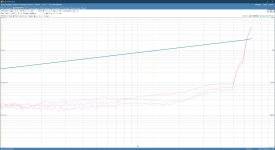
What's also interesting is that by looking at the idle current through the KT88s the distortion drops significantly from 50-60-70mA, see attached measurements, top is 50mA, middle 60mA and bottom 70mA. What doesn't change, which is what I was hoping for, is the point where the distortion starts to climb, around the 20W mark. I kind of hoped this would be the point the amplifier switched to class-B and thus a higher idle current would push that further out. It seems like this however is caused by the input section lacking the needed gain to correct the distortion at higher power.
Attachments
Reason is that amplification is not infinite, thus the right half will have lower plate swing.Why is that? Both on the bench and in the simulator I see exemplary performance with the anodes being within a few 10s of mV of each other, unless you know something I don't?
Some compensates with differing plate resistors, other uses a pot used to minimise
dist ( AC balance)
Better would be to use a concertina that is inherently balanced and needs no adjustment.
A concertina is no guarantee of balance - I've had 12ax7’s that were pretty darn unbalanced. And you cannot get as much voltage swing from one as you can with an LTP.
Does your simulation show the same problem or is it different. Could you zip it up so we can take a look please.
I’m analyzing distortion with measurements on the prototype, at this point the simulation is merely used to check operating points and to try out ideas before modifying the prototype.I think to analyze distortion you need a reasonably accurate match of the transformer - in particular the UL % position. I would also expect that without a CCS in the LTP tail the anode AC voltage swings would be different causing 2nd harmonic distortion. You can get round this by making the plate resistors non equal which will get the AC right and the DC wrong.
There’s no problem, I’m merely asking for suggestions on improving this design further. Things I haven’t thought of, stuff that can’t be found in any of the tube design related books, i.e. practical tips that would show results on the bench. I’d be happy to zip up the simulation though and post it here.Does your simulation show the same problem or is it different. Could you zip it up so we can take a look please.
Looks a lot like a Mullard 5-20, a bullet proof design with a good record.Alright, the subject is pretty self explanatory, I'm at that stage of a design where I'm dotting the i's and crossing the t's. Below is the schematic which represents the status quo of the current prototype with an actual measurement of THD v.s. output power at 1kHz included. I've obviously tried just about every trick in the book, hence the fact this is the 30th revision of the prototype schematics, some revisions were small just a resistor value change, some larger, and I am hoping to get some suggestions on how to improve THD > 20W, as currently the THD rises significantly after that point. I have the prototype on the bench, and the simulation running on the PC and interested to try suggestions, as I'm sure there's still room for improvement! Looking forward to your replies!
So what is the problem? Just build & expect good results. And enjoy.
- Home
- Amplifiers
- Tubes / Valves
- KT88 PP - Dotting the Is, crossing the Ts