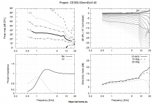
Here is a 50mm exit 15" version of the freestanding CE360. There is a B version for baffle mounting, but simulating that depends on the baffle for a more accurate estimation. The newer development ESP device is intended to help with the upper polar degeneration due to the 50mm exit size. Aragorus made a plug for an Axi2050 but wasn't very pleased with the initial result sound wise. Getting the right waveguide to match with it still required some experimentation or simulation, I don't know if he is still working on it or not.I could ask in Mabats thread but I don't want muddy up his thread with "hey can you please tell me what waveguide to build", as he normally has some really good discussion going geared towards the leading of waveguides. Maybe I am being too polite. At one point in time a person actually had an Axi2050 they were trying to design a waveguide towards....I wonder what came of it....
Attachments
-
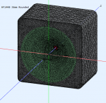
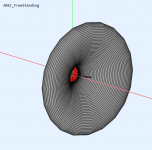 CE360 50mm Mesh.png53.6 KB · Views: 100
 -
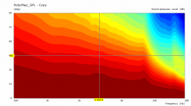 CE360 50mm Polar 0 90 Norm.png25.6 KB · Views: 100
 -
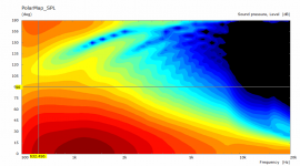 CE360 50mm Polar 180.png41.4 KB · Views: 98
 -
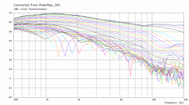
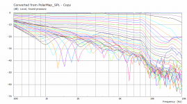 CE360 50mm Polar Curves Norm.png33.8 KB · Views: 98
 -
 CE360 50mm Polar Curves.png31.2 KB · Views: 103
 -
 CE360-50mm Size.png1.8 KB · Views: 95
 -
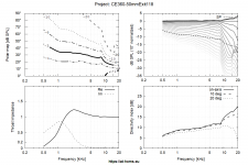 CE360-50mmExit118.png55 KB · Views: 92
 -
CE360-50mmExit118.zip952.4 KB · Views: 77
Fluid you are better than a swiss army knife. I figure 15" makes most sense to match with a 15" woofer. Mounting to a baffle is, the way, isnt it? I have 32" wide baffles.
A 15" waveguide is actually pretty small IMO. I mated a 15" woofer to an 18" waveguide and as low as I could go was about 800 Hz. The upper range problem with the Axi is why I would use a smaller throat. Then the problem go away and you still have enough headroom to match your woofers.
Like a Leatherman, plenty of options to get you out of trouble (except none of them work as well as the real thing) 🙂Fluid you are better than a swiss army knife. I figure 15" makes most sense to match with a 15" woofer. Mounting to a baffle is, the way, isnt it? I have 32" wide baffles.
Mounting to a baffle is different, the Freestanding guide offers some benefits in simulation. The Baffle could take directivity to a lower level, I would not use a 32" baffle though, make it like Earl did, a bit bigger than the waveguide and then round the edge over so it moulds almost into one. The baffled version is a different curve to make it meet the baffle properly.
Here is the 18" version for comparison just change the length to 140mm in the configuration.A 15" waveguide is actually pretty small IMO. I mated a 15" woofer to an 18" waveguide and as low as I could go was about 800 Hz. The upper range problem with the Axi is why I would use a smaller throat. Then the problem go away and you still have enough headroom to match your woofers.
Attachments
Last edited:
I'm ok with a 18" might be able to do 19 or 20 ....I don't know whats the issue with keeping my baffles nice and same sizey....I'd rather go baffless if not.
Having a lot of extra flat baffle beyond the edge of the guide just doesn't work as well.I'm ok with a 18" might be able to do 19 or 20 ....I don't know whats the issue with keeping my baffles nice and same sizey....I'd rather go baffless if not.
An example of a baffle terminated guide 1.4" throat approx 15"
Attachments
Ending a distributed diffraction termination at less than full space doesn't, it wasn't meant for that. A simulation doesn't show everything.Having a lot of extra flat baffle beyond the edge of the guide just doesn't work as well.
It is a full space simulation with the display restricted to +/-90.Ending a distributed diffraction termination at less than full space doesn't, it wasn't meant for that.
No but I find them more useful that your cryptic one liners that you drop without further explanation.A simulation doesn't show everything.
Another option to round out the pie in the sky simulations that you can't buy in the shops.
A radial finned horn from the house of @docali. No fins shown in the rendering, this one or something like it can be made as big as you can lift into your basement.
A radial finned horn from the house of @docali. No fins shown in the rendering, this one or something like it can be made as big as you can lift into your basement.
Attachments
If this was the actual response I would probably do this to it, then add whatever crossover you want to the midBe my guest.
Attachments
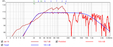
@fluid Ty for taking the time, that looks interesting but my first worry is the peak ~300hz vs the 100hz 2nd order. I will program it and see how it goes.
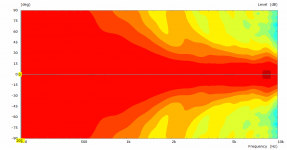
The polar of the waveguide and radial sure are eye candy.


I think I am more interested in the waveguide, since I already have horns.
The polar of the waveguide and radial sure are eye candy.
I think I am more interested in the waveguide, since I already have horns.
Last edited:
With a simulated 80Hz 24dB crossover there is not much of it left, it could be removed completely with a PEQ or a steeper or lower crossover.@fluid Ty for taking the time, that looks interesting but my first worry is the peak ~300hz vs the 100hz 2nd order. I will program it and see how it goes.
You could also keep the 12dB rolloff. With two 18's I can't see any reason why not to.
Whatever float's your boat but you don't have a horn like that 😉I think I am more interested in the waveguide, since I already have horns.

Like fluid said.....and you can also use the technique of adding out-of-band PEQ's to attenuate any peaks that still may show up after xover is applied.@fluid Ty for taking the time, that looks interesting but my first worry is the peak ~300hz vs the 100hz 2nd order. I will program it and see how it goes.
Hi Rob, yeah looks totally reversed .Is it me or should the high and low pass be reversed?? Never used the program. I would expect a 20Hz high pass and 80Hz Low pass to do that. Just looking at a dummy load vs. sim filter response.
Rob 🙂
I asked AllenB to show the raw response of the driver he used, to try to make sense of it. (the sim in #9502).
But got no reply. I suspect the driver's response is far removed from reality...
This is (noticeably) an ideal plot. Ideal plots eliminate variables to make a single point clear. The driver is meant to be the 80Hz high pass in this case. In a real situation, this one filter it isn't normally used on its own, but that goes without saying.Please show the raw response of the driver it took to pull that off.
OK Fluid, well played

I have this saved and can move forward from there, Ty for that. In the end this version also required gain BTW. Just not as much. I was also able to get similar results with my config using 2 filters versus the 6, I narrowed it down to the other way. Your iteration has better phase performance through the crossband. That is desirable. 11db of gain the top Xo, with a 87.4hz lr12. 17db of gain on the bottom Xo, with a 20.5hz lr12...I think your iteration is better, just more filters.

I have this saved and can move forward from there, Ty for that. In the end this version also required gain BTW. Just not as much. I was also able to get similar results with my config using 2 filters versus the 6, I narrowed it down to the other way. Your iteration has better phase performance through the crossband. That is desirable. 11db of gain the top Xo, with a 87.4hz lr12. 17db of gain on the bottom Xo, with a 20.5hz lr12...I think your iteration is better, just more filters.
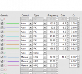
It was a quick auto EQ with some manual intervention so almost always it can be reworked for less filters and a similar response. Depends on how many you have and how much you want to micro manage the response.OK Fluid, well played
I have this saved and can move forward from there, Ty for that. In the end this version also required gain BTW. Just not as much. I was also able to get similar results with my config using 2 filters versus the 6, I narrowed it down to the other way. Your iteration has better phase performance through the crossband. That is desirable. 11db of gain the top Xo, with a 87.4hz lr12. 17db of gain on the bottom Xo, with a 20.5hz lr12...I think your iteration is better, just more filters.
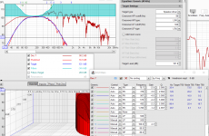
What I would do with the mid is to to chop the top off to get rid of the peaking (set target around 105 dB in your graph) and reshape the response to match the crossover target more closely acoustically. You can do that in Vituix too. Then there won't be so much of a gain mismatch either.
Last edited:
This is (noticeably) an ideal plot. Ideal plots eliminate variables to make a single point clear. The driver is meant to be the 80Hz high pass in this case. In a real situation, this one filter it isn't normally used on its own, but that goes without saying.
View attachment 1018433
Yes, I understand why we use ideal plots....to isolate and to simplify.
But i can't begin to understand how the filters you show, could interact with any driver that is anywhere close to a real world driver.
Again, please simply show the raw response of the hypothetical driver you used that sums with the filters you used in the that sim.
Along with any level machinations if part of the sim.
Teach me, thanks.
- Home
- Loudspeakers
- Multi-Way
- Is it possible to cover the whole spectrum, high SPL, low distortion with a 2-way?