Also good to mention that I ordered the new black board from tea-bag, but I suspect that doesn't change things in this regard.
It will end with ~15 0 ~15 (~30 end to end) and that is what's neededSo attaching the correct ends together an connecting to the 0V/center tap position on the board and the other ends to the 15V position is just fine and the fact that the combined voltage would be 30V is good? That would be a major relief. I have all the data of the built transformer so wiring it correctly is not a problem. Toroidy has a great product and service.
No it doesn't change things in this regard. This new Hypno "Flexsink" board is about heavy duty hot-rod best versatile. Can be used conservatively with onboard sinks but also enhance sound quality if loaded with all four reservoir capacitors and cranked up to heavy bias with external sinks, but it doesn't differentiate AC/DC voltages spec.Also good to mention that I ordered the new black board from tea-bag, but I suspect that doesn't change things in this regard.
Q3 is upside down? No, seems OK. Use of GP is alright.Salas, I am contemplating building the UFSP. Made the schematic and a take on a single sided PCB. But maybe I will go for 2-layer...
I have tried to follow your schematic as good as I can, but could you give it a glance to see if something is terribly wrong? Thanks!
Then about ground plane: is it to avoid on the project, or will it be a benefit?
Edit: Sorry, this came in the wrong thread!
Thank you!Q3 is upside down? No, seems OK. Use of GP is alright.
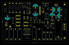
If I decide to produce a proper PCB, how may I accnowlegde you're the author? Is there a Forum Etiquette regarding this? Here is how my PCB might look like (take 1, using big, low tolerance components I happen to have) 🙂
Attachments
For personal use it's alright. You could donate a minimum to the forum to get a title star for a while I guess.
Help.
I have just put together a Salas Hypnotize Flexsink kit on powering up one side of leds dont light up(the three that stand alone and the resistor next to them smokes.Any one have any idea whats gone wrong.
I have just put together a Salas Hypnotize Flexsink kit on powering up one side of leds dont light up(the three that stand alone and the resistor next to them smokes.Any one have any idea whats gone wrong.
Obviously an overcurrent situation. Is the transformer wired the same as to the oppposite PSU polarity side? There are also the TO-220 MUR diodes of the problematic side to check. All DMMs have a diode check mode. Then test the three LEDs. Is one or more of those populated in reverse or broken? You can try light them up with diode check mode again if capable. If not, check them fast with wires from 3-9V battery. No need to remove the MURs or the LEDs from PCB to perform such tests. Power should be off while performing all the above.
Many thanks for reply.
None of the 4 diodes are giving a reading so i assume they are all dead.I did test the one in the audio section which was reading 936 so my meter is working.will try and test leds later with a battery. Not much point though if the diodes are not working.
Cheers Richard
None of the 4 diodes are giving a reading so i assume they are all dead.I did test the one in the audio section which was reading 936 so my meter is working.will try and test leds later with a battery. Not much point though if the diodes are not working.
Cheers Richard
You tested them both ways with the probes polarity? The reservoir snap-in capacitors have correct orientation?Many thanks for reply.
None of the 4 diodes are giving a reading so i assume they are all dead.
See about the three Leds and their associated JFET first before removing the bridge diodes for off board retest/replacement. Because in TO-220 size they are tough components and its odd to be all four of them broken. Especially when one side DC power works.
The orientation symbol for the row of three. Next to where it says 3.3/5W. Cut rim side of symbol/Leds is cathode (-).
Ok then. Since the small CCS components are ok let's go to the big one. Remove the MOSFET next to them and check it with a components tester or some DMM method you may google up. It could have been compromised by static.Yes they do.
Also remove just one TO-220 diode to sample test it off board. One from the problematic PSU polarity side.
- Home
- Source & Line
- Analog Line Level
- Salas hotrodded blue DCB1 build