Drilling the screws holes in the same level of the cannel routing will not put the speaker in the same level? Limiting channel function?All box and horn parts cnc cut. I'm doing it properly with 12mm BB/BB grade baltic birch. Hoping to get them assembled and start filling and smoothing horn entry next week.
View attachment 1014799
No, the difference of a few millimeters in the placement of the 10" speaker entry ports won't make any significant difference in output- it would hardly even be measurable. The photo you posted shows where the 10" should be, just copy the position.Fin and Jenny Girl have been executed your project and i cleary understand that some little differences may have taken place, the channel routing of their project looks like a bit behind the half inch hole.
But the question is: will that make significant differences? Is there an measuremente to where the speaker should be? In my head i'll be using the line of the half inch hole to put the exterior line of the channel routing, is that ok?
You are correct that ab01ns has routed the surround relief channel too wide in the photo you linked in post 961, the driver would fit within the channel, which would reduce potential excursion before the surround would contact the baffle.
That mistake, if not corrected will wear out the speaker surround and make noise before the driver reaches Xmax.
Art
Last edited:
I think it would be the opposite, the more volume the cone filler occupies in the throat chamber, the more VTC (Volume of Throat Chamber) is reduced, the higher in frequency the acoustical low pass filter.Would the cone filler also help attenuate or push up (in frequency) the phase cancellation across the cone?
To safely use the full linear excursion of the cone, the cone filler and surround channel should allow for excursion up to Xmech, which is around twice Xmax. This increases the VTC, lowering the acoustical low pass filter frequency.
Thanks Art!No, the difference of a few millimeters in the placement of the 10" speaker entry ports won't make any significant difference in output- it would hardly even be measurable. The photo you posted shows where the 10" should be, just copy the position.
I would expect maximum output to be less for a box using the 18tbx compared to the 18sw due to the reduced excursion capabilities. Worth checking how much this is and if the reduction in cost is worth it for
Wow, glad you caught that one, silly mistake! I will remake the sides accordingly 😓. Glad I bought extra material.No, the difference of a few millimeters in the placement of the 10" speaker entry ports won't make any significant difference in output- it would hardly even be measurable. The photo you posted shows where the 10" should be, just copy the position.
You are correct that ab01ns has routed the surround relief channel too wide in the photo you linked in post 961, the driver would fit within the channel, which would reduce potential excursion before the surround would contact the baffle.
That mistake, if not corrected will wear out the speaker surround and make noise before the driver reaches Xmax.
Art
Right, but as the driver gets larger in diameter and the "far end" of the driver gets further away from the entry holes, you start getting a notch due to the driver's output going out of phase with itself (I hope I have that correct). So is that an immutable phenomenon that just has to be worked around?I think it would be the opposite, the more volume the cone filler occupies in the throat chamber, the more VTC (Volume of Throat Chamber) is reduced, the higher in frequency the acoustical low pass filter.
To safely use the full linear excursion of the cone, the cone filler and surround channel should allow for excursion up to Xmech, which is around twice Xmax. This increases the VTC, lowering the acoustical low pass filter frequency.
Without a phase plug to make all path lengths from the cone output near and far from the port, cancellation notches will occur. A proper phase plug and mounting for an offset driver would be difficult to construct.
You are correct that the first cancellation notch is at a lower frequency (1.12kHz) with the entry ports further offset from the center of the driver. VTC should not affect that distance related phenomenon.

The port position is a compromise, if placed more towards the center of the cone, (raising the cancellation notch frequency) the center to center distance between left and right cone and horn apex is increased, lowering the cancellation notch frequency, and causing different frequency on and off axis out of phase nulls.
The SynTripP compromise is a "work around" that could be avoided going three way, though that is more work ;^).
Art
You are correct that the first cancellation notch is at a lower frequency (1.12kHz) with the entry ports further offset from the center of the driver. VTC should not affect that distance related phenomenon.
The port position is a compromise, if placed more towards the center of the cone, (raising the cancellation notch frequency) the center to center distance between left and right cone and horn apex is increased, lowering the cancellation notch frequency, and causing different frequency on and off axis out of phase nulls.
The SynTripP compromise is a "work around" that could be avoided going three way, though that is more work ;^).
Art

Is it close enough?
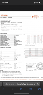
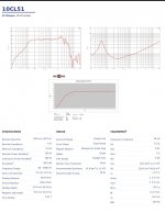
Hi folks, do you think these 10” Triton drivers can kind of replace the B&C one for this project?
It seems they can’t get as low and are not as strong, but they are way cheaper here in Brazil, and since the CD is starting it’s response so low, I thought it would probably be maxed out before these Triton 10” drivers, even though they are not perfect for the horn.
I know the best way to find out is to get them and test it, but maybe someone can find an obvious reason why they wouldn’t work…
I’m attaching both the Triton and the B&C datasheets.
Attachments
Gotcha, thanks for the insight.Without a phase plug to make all path lengths from the cone output near and far from the port, cancellation notches will occur. A proper phase plug and mounting for an offset driver would be difficult to construct.
You are correct that the first cancellation notch is at a lower frequency (1.12kHz) with the entry ports further offset from the center of the driver. VTC should not affect that distance related phenomenon.
View attachment 1017731
The port position is a compromise, if placed more towards the center of the cone, (raising the cancellation notch frequency) the center to center distance between left and right cone and horn apex is increased, lowering the cancellation notch frequency, and causing different frequency on and off axis out of phase nulls.
The SynTripP compromise is a "work around" that could be avoided going three way, though that is more work ;^).
Art
mounting in either quarter space or eighth space
Firstly let me say what a brilliant project! 👍
and so thoroughly and clearly documented and explained. Qualifies for First Class Honours 😉
< I wish I had come across this before last month I bought Altec 90 * 40 multicell horns (1003B’s). I can live with their size. but this has some distinct advantages, and I can’t see any disadvantages.
I can use the Altecs, for the time being … >
I’d like to be clear on their sensitivity when mounted in either quarter space or eighth space. The estimated likely or actual, and the theory. I’m real rusty on this, but recall the change from each “standard” increment in loading is 6 dB. I don’t want to extrapolate that one aspect but ignore something
Situation:
I’m 3/4 through planning changing the living room walls, and could mount these quite modestly sized units * right into the junctions of the walls, and or ceiling, to achieve the full theoretical benefit. to the extent that it applies …
Amplification …
I’ll use a digital crossover and drive these actively. I’m inclined to a tube or small class-A amplifier on the compression drivers, maybe even a 45 SE (Just one very good watt). While for the 10 inchers I’m open to using anything from an 845 SE (16 good watts)/ a 60 watts NP class-A Aleph 5/ Bryston 4B/ class D.
soon I want to decide * which low powered tube amplifier project to mate with these CDs …how much power do I need? (The SPL at distances maths is understood) And any comments on what output/ other they should they * sound best * with. Ie optimised for the SynTrips (which should also be fine for the Altecs)
Post 1 gave their nominal sensitivity at 100 Hz is 99 dB into half space, and 92 dB into free space. I began to think: into quarter space plus 6 dB so ~ 105. And corner loaded ie eighth space plus a further 6 dB, a total of 12 dB so 111 dB. Wow!! But
The SynTripP being ~ 90 * 40, if my 3-D visualisation is working today, that is already a little less than a half of eighth space. So no benefit?
- Theory: the benefit from mounting these into quarter or eighth space. I’m guessing the theoretical plus 12 dB only applies frequencies up to X Hz, then there’s a transition range, and from frequency Y up there’s no gain. What are X and Y?
- Actual: what higher sensitivity would we get when mounted like that?
I apologise if this has already been covered!
Otto,The SynTripP being ~ 90 * 40, if my 3-D visualisation is working today, that is already a little less than a half of eighth space. So no benefit?
- Theory: the benefit from mounting these into quarter or eighth space. I’m guessing the theoretical plus 12 dB only applies frequencies up to X Hz, then there’s a transition range, and from frequency Y up there’s no gain. What are X and Y?
- Actual: what higher sensitivity would we get when mounted like that?
I apologise if this has already been covered!
Pat Brown covered it here:
https://www.prosoundtraining.com/2011/08/29/how-boundaries-affect-loudspeakers/
Your Altec 1003B multicell horns could be turned into MEH (multiple entry horns) by adding a speaker baffle (and box) top and bottom, then drilling entry holes in a radial arc. Those 300Hz cutoff horns could be crossed over low enough to use 10", 12" or 15" drivers that reach lower than the drivers used in the SynTripP.
Efficiency could be quite a bit higher, tube amps in the 15 watt range may be plenty for the low end.
That could fit in a corner much more effectively than the rectangular SynTripP box.
Multi cell multiple entry horn. A thrilling idea for a project. In my opinion, it is not really worth it to modify the multicells - a) 300 Hz-ish crossover is low enough in my book, b) resale value would lower considerably. For home use I would personally follow one of mark100's designs - these would fit the corners as well.
Thanks, ArtOtto,
Pat Brown covered it here:
https://www.prosoundtraining.com/2011/08/29/how-boundaries-affect-loudspeakers/
Your Altec 1003B multicell horns could be turned into MEH (multiple entry horns) by adding a speaker baffle (and box) top and bottom, then drilling entry holes in a radial arc. Those 300Hz cutoff horns could be crossed over low enough to use 10", 12" or 15" drivers that reach lower than the drivers used in the SynTripP.
View attachment 1019756
Efficiency could be quite a bit higher, tube amps in the 15 watt range may be plenty for the low end.
That could fit in a corner much more effectively than the rectangular SynTripP box.
That’s certainly a creative solution I hadn’t imagined but I see your logic. However the OP was right that it would devalue the horns multi cells. That might not be a concern if I pick them up cheap, but I didn’t, and as they are going to be my endgame - which will be MEHs - I need to preserve their resale.
and especially thank you for the link to the article by Pat Brown. It was a good combination of theory and practice which set me straight, and made me realise the fundamental flaw in my logic.
he’s also posted an excellent article about the Schroeder frequency (which I found much better than the one I had previously read by Seigfried Linkwitz). An excellent blog 👍🏼
Attachments

Thank you, PelanjMulti cell multiple entry horn. A thrilling idea for a project. In my opinion, it is not really worth it to modify the multicells - a) 300 Hz-ish crossover is low enough in my book, b) resale value would lower considerably. For home use I would personally follow one of mark100's designs - these would fit the corners as well.
Especially your second point nailed it
I searched mark100 for a while and eventually found his three-way MEH SYN 9 which also sounds * very promising good. 👍🏼
A member called Finbot used 4 Syntripp and 2 tapped horns for bass to provide sound for 3000 people outdoor. It raised alot of concern, but he was adamant it was 3000 people. Its the bass he complained about. You should find his comments if you search for his comments under his username. I will post the video link and description for you.I know someone has to have asked this already but what would be the best driver/speaker option for the most spl? I'm planning on using a pair of SyntripP with 4 keystone subs and I'm hoping to be able to still do heavy metal concerts at large clubs if possible.
4 Syntripp + 2 TH for 3000 outdoorFootage from hosting 3000 people on our mobile artcar. Two main SynTripPs running somewhere near RMS, and two for filling in front at -10db.
Bass provided by two XOC1 TH118 with B&C 18SW115.
Last edited:
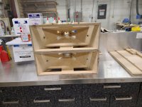
Hi Patrick.A few more progress pics. It's starting to come together.
Today I dry fit the primary horn and thankfully it all snapped together nicely. I think if I build a second one, I will add a bit more clearance in the dado slots for the pole box. The wood glue adds enough thickness that my .005" clearance is a bit tight in that area.
I'm thankful I took the time to add the dado slots and pre-tap the pilot holes on the CNC. It really makes getting all the horn angles lined up much easier. I don't know that I have the necessary skill to assemble this without the assistance of those features. This is my first DIY speaker build and it is not exactly a beginner-level project. I have gained a lot of respect for Art and the others who have built this before me.
Next up is the throat adapter plate. The plan is to mill it from two pieces of 1/4" aluminum plate. We'll see how that goes - I've never tried doing any curved-surface milling in aluminum.
Patrick
Your project looks amazing. Any chance of sharing your Fusion 360 file?
Colin.
Small updates: made more CNC Baltic phase plugs for some syntripP friends across the globe and prototyped out the secondary horn. Primary horns and primed and waiting wet sanding and finish coats. Unfortunately, I am waiting for woofers to become available again in Canada so I can continue on building and start measuring and calibrating. I did however get one assembled with just primer on it to give it a little test. The entire house shakes with -25db headroom to spare so I think I am doing something right here


- Home
- Loudspeakers
- Multi-Way
- SynTripP: 2-way 2-part Virtual Single Point Source Horn