Pass DIY Addict
Joined 2000
Paid Member
A TVS isn't really a "filter" device, it's an over-voltage clamping device to prevent power surges. C1 and C2 as shown in the schematic you posted are built into Mark's power filter and are implemented in a better manner.
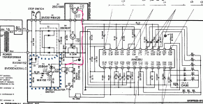
I have a SL-D3 that I am looking at doing the power supply modification on. Looking at the attached diagram, it looks like the TT strobe is being powered by 60Hz A/C through Q3. I do not use the strobe, I actually built a separate strobe that is used for fine tuning pitch. Problem is, I'm not sure the speed selector switch will work if I don't power the strobe LED. Thoughts?
Attachments
Looking at the diagram closer looks like it is picking up power for the strobe through Q1, just the base is being switched by the AC, converted to pulsed DC. I would rather someone who is better at interpreting electronics diagrams verify that, if I supplied DC from an external supply and removed D1 and installed jumpers in it's place, it would operate as normal without the strobe flashing.
Pass DIY Addict
Joined 2000
Paid Member
There is no AC voltage present at Q3 or your at the strobe diode. The traces for all three legs of Q3 and D7 are after rectifier diodes in your power supply. I'm making a guess here, but it looks to me that speed control is determined by the trimmer-resistor vales in VR1 and VR2 that are fed into pin 24 (among others) of the IC. I might guess that the circuit would work without D7, but again, I'm making a guess here, not knowing how this overall circuit and IC1 are intended to function.
I suspect others with more experience than I have in this domain may be able to provide more meaningful insight on this.
I suspect others with more experience than I have in this domain may be able to provide more meaningful insight on this.
How would the little brain know if the LED were blinking? I don't see any photo-sensors.not sure the speed selector switch will work if I don't power the strobe LED.
I do see plenty-enough coils to motor the platter and get pips back; count pips/second and know the speed.
Also: the similar-name SL-1650 has a super-similar schematic (minorly re-drawn) but no LED.
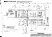
I'm sorry guys, I tend to speak in generalities and was misunderstood because I wasn't clear in my explanation. The strobe light is D7 and does not have anything to do with the speed control. My question: If I (1)remove D1 and apply external DC to D1 and jumper it, (2) remove D2. Will this effect speed selection through S2? After looking at the diagram further J1 on Q1 is supplying 21.6VDC to the speed control selector S2 and to D7, which will no longer work because I removed the base drive to Q3, and I'm thinking speed selection is unaffected.
So the LED goes out as soon as you flick the switch. Otherwise it might flicker on stray charge.why they included the N.C. contacts on S1
Rules when browsing internet:
1. Do not read diyAudio-forum
2. Do not read diyAudio-forum
3. Do not read diyAudio-forum
Because you know what happens....
Around new year I thought to myself that if I don't get myself a SL-1210Mk2 now I'll never will. Things got worse when I stumbled over Varyturn.de. So custom-spec'd SL-1210Mk2 is ordered, the waiting-game is just killing me. So I googled a bit and found this thread, and I knew right away what would happen.
While it would work fine taking the original PSU out and put in a box sort of wasn't enough, I wanted "full control" ie. adjustability. A good friend was needed for the schematic, I drew a PCB and ordered bunch of stuff. Ebay is a money-hog!!
The result came out pretty much as I wanted, very happy with it.

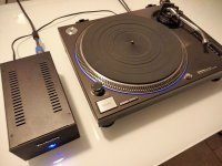
I kept AC on one side and DC on one side:

PCB came out pretty nice too, and it's earthed to case.

Painting a black / Silver case to white was a total pain, turned out nice after all despite using just spray-cans and doing it home. 4-5 coats of matt lack on top to protect it in the future.

I need to blacken out the blue led for the DC-DC drop-down for the front led. The blue shining sort of hurts my eyes 🙂
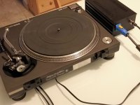
Power-cable to turntable is also taken care of with the principle "enough":

And in case anyone is interested in schematic its here. I ran the PSU through scope, very nice and smooth stuff 🙂

Trafo is 230VAC / 2x15VAC / 2x6A so it's "enough". (Yes, schema says 15VAC in, it should say 30VAC)
Aftermath is always fun:
Q: Why is there a Technics-logo on trafo-shield when it's not visible?
A: I know it's there 🙂
Q: What did it cost?
A: Never count money on hobbies!
Q: Why didn't you get a TimeStep or similar PSU?
A: It's not diy!
There's just one problem, I need to find something to do while waiting for the turntable. Any ideas? 🙂
1. Do not read diyAudio-forum
2. Do not read diyAudio-forum
3. Do not read diyAudio-forum
Because you know what happens....
Around new year I thought to myself that if I don't get myself a SL-1210Mk2 now I'll never will. Things got worse when I stumbled over Varyturn.de. So custom-spec'd SL-1210Mk2 is ordered, the waiting-game is just killing me. So I googled a bit and found this thread, and I knew right away what would happen.
While it would work fine taking the original PSU out and put in a box sort of wasn't enough, I wanted "full control" ie. adjustability. A good friend was needed for the schematic, I drew a PCB and ordered bunch of stuff. Ebay is a money-hog!!
The result came out pretty much as I wanted, very happy with it.
I kept AC on one side and DC on one side:
PCB came out pretty nice too, and it's earthed to case.
Painting a black / Silver case to white was a total pain, turned out nice after all despite using just spray-cans and doing it home. 4-5 coats of matt lack on top to protect it in the future.
I need to blacken out the blue led for the DC-DC drop-down for the front led. The blue shining sort of hurts my eyes 🙂
Power-cable to turntable is also taken care of with the principle "enough":
And in case anyone is interested in schematic its here. I ran the PSU through scope, very nice and smooth stuff 🙂
Trafo is 230VAC / 2x15VAC / 2x6A so it's "enough". (Yes, schema says 15VAC in, it should say 30VAC)
Aftermath is always fun:
Q: Why is there a Technics-logo on trafo-shield when it's not visible?
A: I know it's there 🙂
Q: What did it cost?
A: Never count money on hobbies!
Q: Why didn't you get a TimeStep or similar PSU?
A: It's not diy!
There's just one problem, I need to find something to do while waiting for the turntable. Any ideas? 🙂
Thank you @6L6, I just finished the PSU mod and rewired tonearm. Thank you @peppennino, I bought this PCB for the PSU. Thank you @calipilot227 ,I bought the same cork mat. I don't like breadboards. So I bought the DC1200 Regulator for KAB.The PSU mod will make you reassess everything you think you know about the 1200. It’s really that good.
Change mats to cork or acromat, and then do something to address the feet, and you have a deck that will stand with any. 😀
Thank you. The speakers are Falcon Q7. The phono preamp is VTA-PH16. The preamp is VTA-SP14. My LS3/5a with Dynaco ST-35/VTA-SP10 in the office room.Very nice job 👍
Dynaco and 3/5: a match in heaven!
Or in Space, if you prefer
View attachment 1029661
I notice everyone uses a CRCRC. Is there a technical reason why no one uses a RCRCRC? I would think it would prolong the life of the first capacitor that see's most of the ripple and you would gain an extra RC filter in series.
So a capacitor right after the rectifier does a better job of smoothing the load current variations instead of a resistor then capacitor right after the rectifier?
Looks very nice, how dod you do the sub plateau lighting?
- Home
- Source & Line
- Analogue Source
- Technics SL-1200 DC Power Supply
