Most regulators have protection circuitry anyway.
When I drop several cold heaters onto an LT1084, it limits the output and the voltage ramps up slowly. Same with the MIC29300.
When I drop several cold heaters onto an LT1084, it limits the output and the voltage ramps up slowly. Same with the MIC29300.
Doh, didn't see that at first. Wasn't aware of the LM74670, thanks.I think the LT4320 works only with 9V and above. I was looking into it, but then for that reason went for a design with 4 LM74670s.
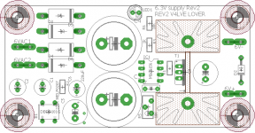
Time for a resurrection, i made another version of my 6.3VAC=>6.3VDC boards. Gerbers are attached, cant be asked to do a bill of materials sorry. And notice: I havent ordered this version yet.
Attachments
May have missed it but did anyone suggest running a simple full wave voltage doubler off the 6.3V winding follewed by a 3-terminal regulator?I’ve been testing various options for creating a clean and stable 6.3 Volt DC from the 6.3 Volt AC heater transformer winding. Why DC? I discovered earlier that DC on the driver tube’s heaters did lower the residual hum and noise of my tube amplifier. Even though the hum was inaudible I could still measure some.
Therefore I use DC for two 6SN7 tubes per channel in my amplifier. This means each channel draws 1.2 A average heater current, with of course a current surge for cold tubes when switched on.
Of course this solution can be used for lots of other tubes with a 6.3 volt heater.
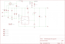
I started with rectifying the AC voltage with a full Schottky bridge, using SB540 diodes. These fast switching diodes can do 5 A up to 28 Volts AC RMS with a voltage drop of approximately 480 mV with full load. The bridge is feeding 3 capacitors of 22000 uF each (66000 uF in total).
Of course I could use the raw voltage for the 6SN7 heaters. But I wanted to do better than that, by adding some sort of regulation.
I tried with a LT1084 regulator at first, because I had them lying around. With 1.2 A load, the voltage dropped to 6.2 Volt. This will work quite OK, but we’re at the limit of the LT1084 as far as regulation is concerned.
Next I tried a XL6009 DC-DC Step-up boost converter, as sold very cheap on Aliexpress and Ebay. It worked for a while, but the output voltage can only be set with the appropriate load. This means when you only have one of the two tubes inserted for whatever reason, the remaining tube will get a lot more than 6.3 Volt. I further noticed the output voltage was not always stable. On these cheap boards the XL6009 chip is not cooled, so there we have another issue. I abandoned the idea of using two of these cheap boards in this project.
Then I came across the Microchip MIC29303WT Low Drop regulators. I bought mine from Mouser and made a prototype PCB for two regulators on a single heat sink. The heat sink is just a piece of thick aluminium.
The MIC29303WT is the adjustable type of the MIC29XXX range, with a current rating of max. 3 A. It’s using a 5 pin TO220 package. For adjustability I added a 500 Ohm potentiometer (R1 in the datasheet and in the diagram below). The combination of this variable resistor and the 100 Ohm fixed resistor (R2) is just enough minimum load to get a stable output voltage. According to the datasheet we should expect approximately a 250 to 300 mV voltage drop with a 1.5 A load. Not bad for such a cheap device!
Due to the cold tubes current surge I use two regulators, one for two 6SN7 tubes.
The MIC29303WT has an Error Flag connection, which signals output out-of-regulation. It can sink up to 10 mA, so I added a LED with a resistor in series to make use of this option. The LED blinks when the unit is switched on and off, so it’s working! I also added a green LED to show that the output voltage is present.
The most important thing is of course if we get the 6.3 Volt DC? And does it regulate properly? I made some measurements and the results are even better than expected.
Not shown in the schematic diagram, but visible on the picture is a 47 Kohm resistor. This is added to allow heater elevation by elevating the minus contact of this board to a voltage of approximately 40 volts from the main power supply.
I also tried to make some basis measurements for residual AC (hum/noise) on the output. Unfortunately I had quite long measuring leads, so I measured 0.6 mV with the power off. When I switch the power on I cannot measure any increase of the AC. I haven’t had time yet to make further measurements with my spectrum analyzer.
Happy DIY!
Gerrit
Hi John,
I’ve tried that with quite a few 3-terminal regulators, but the voltage dropped too much.
With Schottky diodes and the 5-terminal regulator everything is running fine, and very cool too.
What regulator would you have used?
Regards, Gerrit
I’ve tried that with quite a few 3-terminal regulators, but the voltage dropped too much.
With Schottky diodes and the 5-terminal regulator everything is running fine, and very cool too.
What regulator would you have used?
Regards, Gerrit
The issue with the full wave voltage doubler is that the internal impedance is too high. It is best for low load conditions.May have missed it but did anyone suggest running a simple full wave voltage doubler off the 6.3V winding follewed by a 3-terminal regulator?
There used to be a 10A TO3 jobby in the 80-90''S LM196K i still have two pulls somewhere.
BUT these NPN jobbies will never give the same dropout performance of some of the PNP/mosfet pass devices posted here. They are however inherently much more stable. Example Gracia, the 1085 family of LDO's will work to 1.1-1.4V dropout depending on manufacturer however most require 150uF output capacitance to remain stable.
If there is interest, i can build another batch of regulators and offer them in the swap meet. i still have 20PC of MIC5156YN to play with.
Hi John,
Input-to-output voltage differential Output current is min 3 Volt according to the specs. This is too much for my purpose. The output with my load (2 x 1.2 A) would come below 6.3 Volt DC.
Regards, Gerrit
Input-to-output voltage differential Output current is min 3 Volt according to the specs. This is too much for my purpose. The output with my load (2 x 1.2 A) would come below 6.3 Volt DC.
Regards, Gerrit
Hope you don't need the TO3 version. Nearly $90 each now!
This is a tough nut no matter how it is approached. The full wave doubler on the surface looks like a way out. But it has poor voltage regulation vs load. Not surprising, it is composed of two half wave rectifiers with their output connected in series. The CT rectifier circuit is also that kind if we think about it.The issue with the full wave voltage doubler is that the internal impedance is too high. It is best for low load conditions.
The full bridge connected direct to the filament transformer solves that problem. But might result in too little volts to work with.
Both solutions result in very large RMS currents in the transformer windings leading to excessive heating.
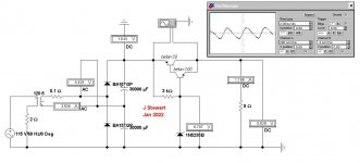
Here is a voltage doubler solution. The resulting RMS current in the transformer secondary is more than 3X the DC current to the load. Something to be aware before starting. I’ve used this odd looking ‘Darlington’ connexion so that only one base-emitter drop occurs between the reference & the load. I’ve assumed beta’s realizable at the load involved. Many transistors would do better, so this is a worst case.
Ge devices would do a lot better. But no longer readily available.
The scope trace is both before & after the ‘Darlinton’, one trace behind the other. Electronic Workbench does not make provision for different colors which would help us. On the scope front panel the incoming signal attenuator is set at 200 mV/div while the other is set at 2 mV/div. so the ripple is reduced by a factor of 100. Some filtering of the supply to the Zener would help. Or supply the Zener with a 2-term current source.
Think I’d look for a common 12V, low cost transformer & use a full bridge rectifier as the basis. If I had too. But I’ve never had problems with power line hum thru AC on the first stage of any power amp I’ve built. But OTOH, I’m not a critical listener. As long as the Rolling Stones & Pink Floyd are rockin’, I’m OK.
Attachments
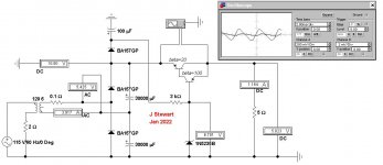
The Reference Zener gets a smoothed supply. Something I built into several regulated PSs I built in the 50s & 60s,This is a tough nut no matter how it is approached. The full wave doubler on the surface looks like a way out. But it has poor voltage regulation vs load. Not surprising, it is composed of two half wave rectifiers with their output connected in series. The CT rectifier circuit is also that kind if we think about it.
The full bridge connected direct to the filament transformer solves that problem. But might result in too little volts to work with.
Both solutions result in very large RMS currents in the transformer windings leading to excessive heating.
Here is a voltage doubler solution. The resulting RMS current in the transformer secondary is more than 3X the DC current to the load. Something to be aware before starting. I’ve used this odd looking ‘Darlington’ connexion so that only one base-emitter drop occurs between the reference & the load. I’ve assumed beta’s realizable at the load involved. Many transistors would do better, so this is a worst case.
Ge devices would do a lot better. But no longer readily available.
The scope trace is both before & after the ‘Darlinton’, one trace behind the other. Electronic Workbench does not make provision for different colors which would help us. On the scope front panel the incoming signal attenuator is set at 200 mV/div while the other is set at 2 mV/div. so the ripple is reduced by a factor of 100. Some filtering of the supply to the Zener would help. Or supply the Zener with a 2-term current source.
Think I’d look for a common 12V, low cost transformer & use a full bridge rectifier as the basis. If I had too. But I’ve never had problems with power line hum thru AC on the first stage of any power amp I’ve built. But OTOH, I’m not a critical listener. As long as the Rolling Stones & Pink Floyd are rockin’, I’m OK.
Attachments
Xl6009 as many sepic or buck boost converters has a typical problem .They need either lower or higher input voltage than the output voltage in order to meet the specified efficiency.If the input voltage is found within in a 3 V window around the output voltage the efficiency drops below 70% or simply throw it in an unstable on off regime.You'll get this behavior from almost any buck boost converter when the difference between input and output is too small.
Also, the diodes used on the usual kits are 1 amp diodes so they can't really give 4 amps output.
Also, the diodes used on the usual kits are 1 amp diodes so they can't really give 4 amps output.
Another problem with the XL6009 is the enormous voltage drop when you load the output. My curent regulator as described in post #1 is very stable and the XL6009 is no longer an option for me. The diodes however did survive my 1.5A test load.
Regards, Gerrit
Regards, Gerrit
Gerrit, I am about to build the MIC29303T in my amplifier. The load will be 1.2A. One question: the datasheet recommends a 10uF capacitor at the input and a 22uF capacitor at the output. How critical are these components? There is already a big capacitor at the output of the diode bridge, so the input capacitor seems redundant. I don't see one on your photo in #1 either.
I will report about its performance in a couple of days.
I will report about its performance in a couple of days.
Hi Icsaszar,
I have a 47 uF at the output (because I had these available). On the input I only have the big smoothing ones. In fact my Schottky bridge and the 3 large capacitors are on another board, connected with short shielded wiring to the regulator board. I just had no room for a single bigger board, so I had to use two smaller boards.
I think your regulator will work just fine if you have sufficient capacity on the input side and let’s say a min. value of 22 uF on the output.
Good luck with your build and pleas report your findings here later. Much appreciated!
Regards, Gerrit
I just quick checked it unloaded. The raw AC is 6.9V, rectified with 4x 1N5822 Schottkys the DC at the capacitors (2x 6800uF/16V) I get -9.1V. Output from the regulator is 6.3V. Drop is 2.8V. There is a few mV random noise at the output. Tomorrow I will check it loaded with tubes (2x 0.3A + 1x 0.6A).
Hi Icsazar,
Good to see it’s working. Did you use my values for R1 and R2? These should be OK, just as they are for me, but understand that the values for R1 and R2 determine the output voltage.
Check the specs, for example at:
https://nl.mouser.com/datasheet/2/268/MIC2915x_30x_50x_75x_High_Current_Low_Dropout_Regu-1889172.pdf
When changing the values for R1 and R2 for any reason, pleas keep in mind they are used as a minimal load on the output too, according to the same specs.
Regards, Gerrit
- Home
- Amplifiers
- Tubes / Valves
- Get regulated 6.3 VDC from 6.3VAC