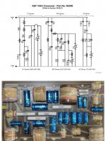
Absolutely none of the YouTube vids shows two boards, but a cutaway of the model does show it! My next step is to take the seven caps off the board and test and replace them. Here’s the cutaway.

Some versions had separate boards, i believe they were the later models with bi-amp capability. If you think about, you have to have separate crossovers to do that. The schematic is probobly very similar if you just copy it up into sections. Only additional complication is they added more protection circuitry into the later models.
Attachments
I only have one pair of inputs, so no bi-amp capability. The speakers were probably bought in 1986. I’m waiting on the ferrofluid to redo the tweeters. Took one tweeter apart. Piece of cake.Some versions had separate boards, i believe they were the later models with bi-amp capability. If you think about, you have to have separate crossovers to do that. The schematic is probobly very similar if you just copy it up into sections. Only additional complication is they added more protection circuitry into the later models.
Can you supply a little more detail? I don’t see how I can use this to test a 50 volt cap with that low of an output. And I certainly wouldn’t want anything to kill my computer.No specialized precision equipment, a multimeter able to measure from 0Vrms and up, one resistor, a laptop headphone out, a sine wave frequency generator software (REW) and some hook-up wire (mini mono or stereo plug). After that some calculations and you are done.
You are lucky cause the standalone board filter version can not be checked without removing the top woofer.
First you should draw each circuitry on paper, better to understand the protection circuitry. But this last is for the tweeter only I surmise.
What is the thing at the left of the woofer pcb near the left legs of the caps? A diode ?
Culpritt is not a cap while they should be changed for fresh now as the values have drifted.
Try first to check the protection circuit and that part on the woofer pcb. Draw a shematic of the bass pcb in order we can help you more and understand where þhe current flows from the binding posts till the woofer first
Two tools are needed: a voltmeter and a capacitormeter, both are cheap, 30 bucks each for basic, that is enough.
The caps values are a little different at some area from the former standalone pcb model.
Hummm if the white and black wire are comming from the binding posts then it means all is passing first to the protection circuitry...the blue relay or the red encapsuled zener should be the cause. No worry it can be bypassed if you do not use your speaker for party and refluid the T33s.
That component is a 8 ohm resister and it reads good. Unfortunately, the protection circuit can’t be diagramed. It has two wafers coated in a red plastic that you can tell are multiple components on each wafer. The good news is that portion of the board is past the woofers. It’s function is to cut power at this board to protect the midrange and tweeter. It has nothing to do with the woofers. I have already sketched out the circuit. See below. Also note it doesn’t in any way fit the LF portion of the single board crossover.

Have you checked the colors of wires at the bottom of the loudspeaker insise the cavity, it should be below a green grey foam ? Are they really red and white at the binding posts or white and black ?
I do not recognize the shematic, maybe a drawing error or a serie filter ???
The 104/2 I know is the shematic given in a post above. I would check all the caps in the woofer circuitry that are shunted to the gnd aka return path black connector.
On your photo where are going the white and black wires ?
The binding posts are screwed on the woofers filter pcb ? The two little rods at the bottom of the pcb in middle position below the Alcaps ?
The posts on the back of the speaker are bolted to the two holes in the bottom of the board in question. The black and white wires carry in audio input to the crossover for the midrange and the tweeter. The blue and grey wires are also on that crossover board and they signal an overload which then opens the relay to save the tweeter and midrange.Have you checked the colors of wires at the bottom of the loudspeaker insise the cavity, it should be below a green grey foam ? Are they really red and white at the binding posts or white and black ?
I do not recognize the shematic, maybe a drawing error or a serie filter ???
The 104/2 I know is the shematic given in a post above. I would check all the caps in the woofer circuitry that are shunted to the gnd aka return path black connector.
On your photo where are going the white and black wires ?
Ok, check the 600 uF and the two caps below, i.e the 3 upper caps on the pcb. Resolder the vias on those three caps...maybe a cold joint. Check idem with the buzzer for the coils. Anyway one of the cap should have a problem, they are too old... you will not recognize the sound with brandnew ones 🙂.
The four first above the bolds (240 uf//240uf + serie100 uf)//100 uF are the high pass towards the mid tweet pcb and are ok.
Be aware than the recap kit from Falcon is for the standalone pcb. Alcaps seems to have problem perhaps as the caps are more and more difficult to source at Falcon...their Alcaps catalog melted down halas.
Last edited:
Check also where are going the purple and the orange wires. They are the signals cables of the woofers after the 2 low pass coils. One is going to the neg post of the upper woof, the other is going to the positive of the bottom woof. Important to check for their push pull working or you will have bass cancelation,
A bone fide version then! - i understand some had boards underneath the lower woofer though most a single board at the back. The owner of the pair i did with as many mkp's as practical for small budget is continually raving about how much better they are.I only have one pair of inputs, so no bi-amp capability. The speakers were probably bought in 1986. I’m waiting on the ferrofluid to redo the tweeters. Took one tweeter apart. Piece of cake.
I do think lythics in shunt position should stay lythic due to their esr for damping reasons. The low loss marked LL could eventually be swapped for MKPs, rest in serie with MKTs. It is hard due to the poor area room but for the treble values.
I never found the 600, 240, 450 uF in bipolar, I had to // two each time.
I never found the 600, 240, 450 uF in bipolar, I had to // two each time.
There is a thread covering how one might measure impedance using ARTA and/or REW. Post #4.Can you supply a little more detail? I don’t see how I can use this to test a 50 volt cap with that low of an output. And I certainly wouldn’t want anything to kill my computer.
https://www.diyaudio.com/community/...edance-curve-measurement.311461/#post-5165552
Another way of finding out unknown L or C is to use a smart phone as a sound source.
Attachments
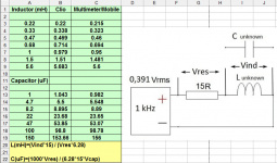
I suceeded to trace the impedance curve of a coil with Arta and my diy Arta box ...but it is not giving you the L value. You need to do math....
Falcon is very difficult to order from. Their website doesn't spell out the caps that come in the kits. Jerry Bloomfield is pleasant enough. He asked for a list of the cap values to do one speaker and he said he would make sure the kit contained them.
I took the three caps completely off the board and experimented with a 9 volt battery. The 240 mfd cap that sits between the input and the 0.8 ohm resistor wouldn't hold 9 volts for any time. By the time I disconnected the battery, the voltage on the cap dropped to 5 volts and then continued to bleed off from there. The other two caps, the 600 and the 450 are still at 9 + volts when I touch the ohm meter leads to the cap. Of course, at that point, they start to bleed off. It amazes me that I can't find one 240 mfd capacitor rated at 70 volts anywhere in the world except for Falcon. And they want me to buy the entire kit at more than $130. And that's without shipping from the UK....
I took the three caps completely off the board and experimented with a 9 volt battery. The 240 mfd cap that sits between the input and the 0.8 ohm resistor wouldn't hold 9 volts for any time. By the time I disconnected the battery, the voltage on the cap dropped to 5 volts and then continued to bleed off from there. The other two caps, the 600 and the 450 are still at 9 + volts when I touch the ohm meter leads to the cap. Of course, at that point, they start to bleed off. It amazes me that I can't find one 240 mfd capacitor rated at 70 volts anywhere in the world except for Falcon. And they want me to buy the entire kit at more than $130. And that's without shipping from the UK....
yup, and it is without the 5% to 20 % of precision if you'd find them ! If you buy several 220 uF hoping 4 will be near 240 uf it becomes quite expensive with those values (while if you find two of 225 uF you have your 450 uF by //... but there will be esr mismatch then it becomes quite expensive fast. And unluckilly mkp or mkt caps are huge in that values.. At the end Falcon kit is ok but too much expensive with only 5% or more precision todays cause they have no more stock for the 2%.
It is not clear on the official Kef filter shematic if the caps marked 10% precion on the picture means it is ok if staying within 10% : some caps have capacitance value without any % margin... I do not know if that lasts are the 2% advertised and matching for the L&R cabinet Kef advertised ?!
you can make your POC with two 300 uF for the 600 uF and 220 uF instead the 240 uF to know< if the problem comes from one of the three caps but any way you will need to refresh the whole filter boards !
Last edited:
To look for an exact duplicate of an old npe capacitor is a wrong thing to start with. There is plenty equivalent caps in the word that are cheap enough no one could possibly complain about. If I had to buy one, I would go to an electronics store and measure a couple of these from a lot and choose one. In Croatia you get that privilege if you can manage it.
- Home
- Loudspeakers
- Multi-Way
- KEF 104/2 cap replacement