Has anyone had any experience with using a dual power supply for tube amps? If so, did it work? If not, why not? I ask because It seems to me (at least in theory) that it would bypass the problems of having to use hv caps if one could split up the b+ into a negative leg and a positive leg.

Thanks for your reply. Kindly give me a block diagram for a dual power supply for a two tube amp. I can't imagine where/ how to attach the negative leg on v2 if B+ goes into the plate.
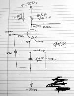
Thanks again for your reply. My question is about the voltage. Please review the attached to determine if it would/should work. If not, why not? Let me say at this point, that I have put it into the circuit and so far, my 50W cathode resistor heats up and starts to smoke and I don't know why. Thanks for any help
Attachments
Ok, what is the measured DC voltage at the plate and cathode before you stop the smoking?
Is your heater supply floating, and not grounded? Can you post the entire schematic, including power supply?
Is your heater supply floating, and not grounded? Can you post the entire schematic, including power supply?
I will get the voltages as you requested later, but for now, the answer to your other question is: the heater supply is floating.
Ok, is the common connection of the two power supply voltages connected to ground,
along with the audio input and output grounds?
Have you verified the values of the resistors by measurement?
along with the audio input and output grounds?
Have you verified the values of the resistors by measurement?
The common connection to the two power supply voltages is the center tap of the single power transformer and that goes to ground. The audio input and output for the whole circuit are also connected to the center tap and therefore, to ground.
Should the filament supply also go to this same ground?
Should the filament supply also go to this same ground?
I think what we need are simultaneous measurements of the plate and cathode voltages
with respect to ground, which is the common connection of the two supplies.
Do you have two DVMs to measure those?
If you only have one DVM, connect it floating across the cathode resistor and measure the voltage.
with respect to ground, which is the common connection of the two supplies.
Do you have two DVMs to measure those?
If you only have one DVM, connect it floating across the cathode resistor and measure the voltage.
I do. I will measure the two locations as you say and will get back to you later. I will also verify that the filament supply is floating
If the filament supply is connected to ground at any point, that would place the entire -550VDC supply
across the cathode resistor, which would result in 550W dissipation in that resistor, at least briefly until it fails.
If this is the case, the cathode bypass capacitor could be damaged, if its voltage rating is less than 550VDC.
And it is likely that the cathode resistor is damaged from excess dissipation.
Last edited:
Use the negative voltage as ground and do not connect the ground tap to the circuit. Use two caps in series with resistors to balance. If the center tap is not connected it will not have a positive and negative voltage but just a voltage. As such what was the negative is now the ground to connect all signal and power grounds to.
please verify that the filaments of v1 and v2 float with respect to audio ground and with respect to each other. IN other words, no filament supply are connected to each other or to audio ground. Correct?No, the cathode and the filament are identical nodes, so the filament supply must be floating.
Yes, just show the complete schematic.
My guess is that some node of the filament circuit is connected to ground, and so it is not completely floating.
That would place 550VDC across the cathode resistor.
My guess is that some node of the filament circuit is connected to ground, and so it is not completely floating.
That would place 550VDC across the cathode resistor.
Last edited:
Anyone working with Op Amps or DC amplifiers has used dual power supplies.
Easiest way to get there is a full bridge rectifier hung on the secondary of a CT transformer.
I've used it several audio amps. Usually some common +ve HV, say 250 to 450 volts
& negative 150V. No problems at all.
Easiest way to get there is a full bridge rectifier hung on the secondary of a CT transformer.
I've used it several audio amps. Usually some common +ve HV, say 250 to 450 volts
& negative 150V. No problems at all.
This is my first attempt at using a dual power supply. It seems to me that it solves some problems of having to acquire HV caps, etc.Anyone working with Op Amps or DC amplifiers has used dual power supplies.
Easiest way to get there is a full bridge rectifier hung on the secondary of a CT transformer.
I've used it several audio amps. Usually some common +ve HV, say 250 to 450 volts
& negative 150V. No problems at all.
Is it necessary to have the pos and neg legs be an exact mirror of the other? Can one leg be a pi filter and the other a choke filter? IF so, are there any advantages to doing it this way?
- Home
- Amplifiers
- Tubes / Valves
- dual power supply