I didn't say they sound similar, they don't, but there is a similarity in the frontal hemisphere radiation pattern between a 90 degree waveguide and a dipole crossed low enough below the dipole peak to maintain a true dipole pattern, which is what Linkwitz and John K aimed at in their flagship speakers.Could you please elaborate more on how a waveguide speaker sounds similar to an OB dipole?
This image from here shows how the pattern changes depending on the wavelength.
http://musicanddesign.speakerdesign.net/Dipoles_and_open_baffles.html
If the pattern resembles the blue and green over most of the passband this is something like two waveguides back to back might give. Limiting the early side reflections which increase apparent source width but almost always harm pinpoint image placement. If the rear radiation has enough distance to a reflection point it too can avoid damaging the more pinpoint imaging that can be had with reduced early reflections.
OK. I guess this is the part from the previous post I thought meant that they sound similar.I didn't say they sound similar, they don't, but there is a similarity in the frontal hemisphere radiation pattern between a 90 degree waveguide and a dipole crossed low enough below the dipole peak to maintain a true dipole pattern, which is what Linkwitz and John K aimed at in their flagship speakers.
"I don't think of dipoles (that are kept that way through their passband) as wide. They are something like 90 to the front and 90 to the rear. If you can manage the rear wave to delay the arrivals outside the first 10ms or so, the imaging should be quite similar to a waveguide, and with heavy toe in the time intensity trading should work much like it does with big waveguided speakers."
Last edited:
The comment was specifically about imaging and how the radiation pattern and room interaction could explain Ken's findings that he wasn't expecting. Beyond that the overall sound presentation is usually quite different, I did not mean to imply otherwise.OK. I guess this is the part from the previous post I thought meant that they sound similar.
"I don't think of dipoles (that are kept that way through their passband) as wide. They are something like 90 to the front and 90 to the rear. If you can manage the rear wave to delay the arrivals outside the first 10ms or so, the imaging should be quite similar to a waveguide, and with heavy toe in the time intensity trading should work much like it does with big waveguided speakers."
A listening position measurement may be helpful.
I usually make some measurements around the listening position too, and note that DRC, based on listening position measurements, plays some role.
I'm confident that a straight measurement obtained using a masked impulse response, with its comb filtering, doesn't necessarily accord with what's heard. I expect that the the direct arrival masks the reflections. The resulting signal in hearing neurons is not the same linear addition as seen by a mic. Exactly how it differs, I don't know.
I will make more measurements to see if I can get a clue what's going on.
On your point in your subsequent reply about limiting vertical radiation: it's unclear to me how to allow precedence masking to work at its best to reject reflections. First priority must be to avoid strong peaks in the spectrum of the reflected component, J
I suspect most would agree, but after that the relative importance of level and spectral shape is unclear to me (within the range typically seen among speaker designs and small rooms).
Ken
Hi tmuikku,Hi,
As augerpro says listening spot measurement could perhaps show if there is overall smoother response with all reflections combined at listening position with the new xo frequency.
Do you happen to have the system measured and in a VituixCAD project? There you could possibly see what the effect of vertical early reflection is in ideal case and how it changes as you move the xo point. Might help reasoning and device further experiments.
thanks for the kind words. See my replies to augerpro - I'm not convinced about the utility of measuring the comb filtering. As you know, with long enough delay the effect on the perceived sound falls away, but a measurement would still show the comb.
I'd not like to go lower with the crossover, due to the combination of dipole and driver fs. At first I was cautious about even going to 450Hz, but that seems OK. I could try a little lower, but then it's starting to look like the wrong choice of drivers.
I've not got a VituixCAD model for the speakers. Since the design and build time for the physical speakers was ten days, and since then changes have only been in DSP, I mostly do trial and error measurements, keeping trends seen in crude models in mind as a guide.
When you suggest using VituixCAD to assess reflections do you mean through the early reflections curves and Early reflections DI? If so, I think my extrapolated near field measurements of the sound that becomes the various early reflections should contain equivalent information.
Ken
^ By VituixCAD model I mean it is quite easy to change c-c spacing and/or crossover frequencies, system elevation "in room" and see in real time what the effect is to various angles like towards first reflections. There is also very simple "room model" where you can inspect what ceiling or floor does, or both combined.
It is relatively easy to tweak system so that floor and ceiling reflections in VituixCAD make least effect, seen as interference/combfiltering with in-room estimate, but it doesn't tell anything about the perceived sound of course. I've made many sims and can optimize this or that graph but haven't had opportunity try and listen differences of configurations which would actually make for better sound, like you have. Hence the interest 🙂
The simple room model is particularly interesting to watch what happens to in-room estimate, if the system was elevated below or above listening height for example. This is independent of the DI and Early Reflections DI of the speaker. Both can be smooth or have issues, still adjusting in room height of the system has effect. Having mid above listening height for example, gets smoother simple floor and ceiling reflection combfilter combination, not knowing of course if this is important or not for the perceived sound. By smoother I mean that when mid is lower in height (as it usually is, below tweeter) there can be very wide dip on the mids as simple floor and ceiling reflections cause dips quite close together resulting one very wide dip. At least on the experiments with my few projects.
Thanks tmuikku, I see better what you mean now.
From the start, I decided this project would progress without a decade of procrastination. The choice of mid and tweeter and the upper crossover pins down quite a lot of the design. I fixed some other variables such as the shape of the baffle and height of the three drivers early on, largely based on measurements made by others, and a few measurements on test baffles. That leaves the position and angle of the speakers in room, crossovers/DSP, and DRC as the variables.
I could change the mid-tweeter module at some point as it's relatively easy to replace, but at the moment, there's nothing that comes to mind that would be clearly better.
Ken
Yeah I believe so too that there is no reason go exploring after you've found what you came looking for.
What I would have liked to see is what happens with the graphs in simulator as the xo is lowered in your particular system, without touching rest of the variables. Maybe the simple floor and ceiling reflection interference would nicely overlap or something.
There might be something in the graphs that would correlate to what you perceived and would perhaps help others (me) to get closer to in our systems.
I think I need to make my own listening experiments 😀 Carry on, I'll follow.
ps. I have to add that I inspect the VituixCAD sims not just crossover in mind but as visual representation of the whole speaker system in room. Crossover is the trivial part, the graphs can be bent by the construct and room as well which is also trivial in the simulator but not in reality (building + measuremets). It is matter of knowing mentally how the graphs translate into perceived sound to be able to reason over the graphs what needs to be done to get "better" perceived sound for given system and application. Toole and other studies have given out some graphs to use as targets that should work most of the time (like flat on axis, falling power etc), but there are missing pieces, especially with the early reflections I mean, how the smooth DI for example interacts with the room, or would some deliberate kink be better or does it matter at all.
Last edited:
I agree with the ps.What I would have liked to see is what happens with the graphs in simulator as the xo is lowered in your particular system, without touching rest of the variables. Maybe the simple floor and ceiling reflection interference would nicely overlap or something.
There might be something in the graphs that would correlate to what you perceived and would perhaps help others (me) to get closer to in our systems.
I think I need to make my own listening experiments 😀 Carry on, I'll follow.
ps. I have to add that I inspect the VituixCAD sims not just crossover i...
Somewhat along the line of your idea about floor and ceiling reflections adding ...
Looking at some impulse responses I spotted early reflections that I'd not thought about at all: floor->ceiling->listener. Given the proximity of the bass drive to the floor, its reflection follows <2ms behind the direct bass->ceiling->listener reflection. I guess these two reflections coming so close together really do add together in the sense that if one is perceived due to incomplete masking, it's the sum of them that is likely to be perceived.
I don't think I'll be able to gate the measurement to get a single plot that provides convincing evidence, but with various mic locations and sliding the gate around, the total ceiling reflection shows no sign of a significant dip (remember this is measuring at 450Hz with gate-limited resolution around 100Hz). I'll take this as a hint that the dip may be far less significant than I thought yesterday.
What I should really do now is look back at or redo measurements with the higher crossover, to see if the floor-ceiling reflection causes harm in that case. I might have gated it from the measurements without thinking carefully about what it signifies (whether or not it's important). I'll look back, but probably not redo measurements, at least for now.
Ken
I should say that zmyrna suggested I try a crossover around 400Hz some time ago... https://www.diyaudio.com/community/...to-one-forum-member-an-ob.374532/post-6725722I'd not like to go lower with the crossover, due to the combination of dipole and driver fs. At first I was cautious about even going to 450Hz, but that seems OK. I could try a little lower, but then it's starting to look like the wrong choice of drivers.
Ken
Ken
Try a few different gates. In the past on this forum, 50ms or a bit less has been suggested to help produce something that better represents what we hear, given the precedence effect and integration time of echoes.
Wow, I find it amazing that you can use this track to assess any speakers. Just listened to it on Sennheiser HD650s + Okto dac8 and it sounds to me like there's lots of front-end overload on the preamps/mics during the original recording -- or elsewhere in the recording chain. So much harmonic distortion (fuzz box, I presume), how can you differentiate between the musical distortions and the speaker distortions?! 😆 But like you said, different folks, different strokes...Audioslave - Show Me How to Live (Official Video) - YouTube
This is one of my go to tracks for testing speakers, when the chorus kicks in around 1:45 in the youtube video. All my Linkwitz dipoles failed quite miserably. I realize this will not be to everyone's taste but I grew up listening to this sort of thing so if a speaker can't do it justice it isn't for me.
In contrast, this cut makes perfect sense to use as a reference -- good sonic variety, dynamics, capture of acoustic space... etc.In contrast this one has never sounded better than on on the LX521
James Bay - Hold Back The River - YouTube
If you have heard the difference in presentation between tracks like the above on different types of speakers you might appreciate more why they are useful.So much harmonic distortion (fuzz box, I presume), how can you differentiate between the musical distortions and the speaker distortions?!
In contrast, this cut makes perfect sense to use as a reference -- good sonic variety, dynamics, capture of acoustic space... etc.
I think you miss my point and it is one Lynn Olsen has made except he used orchestral music with dense harmonic structures as a torture test.
Nice audiophile style music with space and contrast sounds good on most systems, not always excellent but good. This is why manufacturers play it in their demo rooms. Music like Audioslave or Lynn's dense structured music reveals the problems with speakers very quickly. This was why Lynn was chased away when he bought his own music to the audio show and started to make the speakers sound bad that before had sounded quite good.
Admittedly, I have not heard such tracks on a variety of speakers. If you have, I bow to your greater experience. 👐If you have heard the difference in presentation between tracks like the above on different types of speakers you might appreciate more why they are useful.
But at the same time, despite it being a better recording, I doubt the James Bay piece would sound good on all speakers. It's demanding in its own ways.
Out of curiosity made ideal models of the neo10 and the 14" woofer in Kens configuration, or very rough approximations of, in VCAD diffraction tool.
It looks like ideal planar driver (10cm x 20cm) mimicing neo10 has such narrow vertical dispersion the ceiling reflection is almost no problem. But, there seems to be dip due to floor right around 600Hz for the setting I have here. 90cm listening height (tweeter), the neo10 above and woofer below roughly like picture in the opening post, 66cm c-c between the two.
Attachmens here are 1. ceiling, 2. floor, 3. both reflections with 700Hz LR24 xo. Orange curve on the Power & DI graph is the simplified In-room estimate for 3m listening distance, 250cm room height showing the effect of ceiling and floor. On all of the graphs the orange in-room estimate is what I'm looking at since rest is what it is and can be EQ:d since DI (red line on power & DI window) is smooth, almost flat.
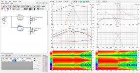
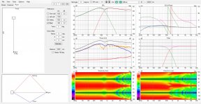
Above graphs show ceiling reflection doesn't seem to have much effect on the in-room estimate with the configuration here. There seems to be enough attenuation towards ceiling reflection (compared to floor reflection) which happens at greater angle. The vertical polar plot is lower right on all of the screenshots. The neo10 planar (ideal) seems to provide very useful vertical and horizontal dispersion in this configuration.
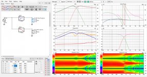
Here is test with lowering the xo frequency like Ken has done. As the xo frequency is moved down the null around 600Hz somewhat changes making it less severe looking, at least more akin to comb filtering on above frequencies. Attachments are 700Hz, 550Hz, 450Hz and 350Hz LR24 xo. Orange in-room estimate shows only floor reflection for now.
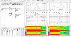
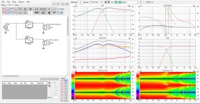
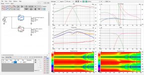
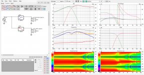
Difference is seen in the simplified floor reflection and could perhaps be one reason of better perceived sound with lower xo frequency.
What tricks can we do? Phases are not aligned on the above test, lets try adjust the frequencies of both filters overlap and play with time delay if there is need to. What happens to the floor reflection? Here is one with 700Hz xo and another one in the lower ~450Hz range.
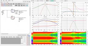
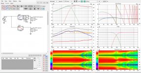
This simple test showed a null around xo towards floor reflection can be manipulated. If height of the transducer(s) and listening distance and xo happens to play together nicely pointing the null can be used as tool to reduce dip due to early floor (and ceiling) reflection. Vertical polar plot shows there is null towards ceiling as well, so that the vertical reflections don't have same frequency response as direct sound. However, the in-room estimate graph is a bit better, no wide dip around 600Hz. Whether this makes sound better, I don't know, but might be since Ken has experienced better sound with roughly similar circumstances and tuneups.
Here is what I ment with that there might be some insight with VCAD sims. Not sure if this would take you anywhere, but was quite easy fast test to see what could be done for floor / ceiling bounce just with playing with the xo frequencies. It seems at least floor bounce gets "improved" with xo adjustment to system height and listening distance and might be one reason why you found better sound with lower xo. Or, perhaps the difference in sound is due to something else and more experiments would be needed to figure it out what it might be.
ps. All polar plots are normalized, ideal drivers were used on ideal roughly similar size structure as Ken's. Room height and listening distance is about typical. Didn't bother to set any filters to straighten up the response. As one sees the DI pretty much flat and response can be EQ:d to liking. I assume the tweeter has narrow dispersion as well and not much of a problem in the vertical reflection context, didn't bother to add that either.
Edit. one more, showing difference as GIF animation for 700Hz xo with phases aligned and what if situation that is adjusted by just looking at the in-room estimate.
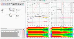
It looks like ideal planar driver (10cm x 20cm) mimicing neo10 has such narrow vertical dispersion the ceiling reflection is almost no problem. But, there seems to be dip due to floor right around 600Hz for the setting I have here. 90cm listening height (tweeter), the neo10 above and woofer below roughly like picture in the opening post, 66cm c-c between the two.
Attachmens here are 1. ceiling, 2. floor, 3. both reflections with 700Hz LR24 xo. Orange curve on the Power & DI graph is the simplified In-room estimate for 3m listening distance, 250cm room height showing the effect of ceiling and floor. On all of the graphs the orange in-room estimate is what I'm looking at since rest is what it is and can be EQ:d since DI (red line on power & DI window) is smooth, almost flat.


Above graphs show ceiling reflection doesn't seem to have much effect on the in-room estimate with the configuration here. There seems to be enough attenuation towards ceiling reflection (compared to floor reflection) which happens at greater angle. The vertical polar plot is lower right on all of the screenshots. The neo10 planar (ideal) seems to provide very useful vertical and horizontal dispersion in this configuration.
Here is test with lowering the xo frequency like Ken has done. As the xo frequency is moved down the null around 600Hz somewhat changes making it less severe looking, at least more akin to comb filtering on above frequencies. Attachments are 700Hz, 550Hz, 450Hz and 350Hz LR24 xo. Orange in-room estimate shows only floor reflection for now.


Difference is seen in the simplified floor reflection and could perhaps be one reason of better perceived sound with lower xo frequency.
What tricks can we do? Phases are not aligned on the above test, lets try adjust the frequencies of both filters overlap and play with time delay if there is need to. What happens to the floor reflection? Here is one with 700Hz xo and another one in the lower ~450Hz range.


This simple test showed a null around xo towards floor reflection can be manipulated. If height of the transducer(s) and listening distance and xo happens to play together nicely pointing the null can be used as tool to reduce dip due to early floor (and ceiling) reflection. Vertical polar plot shows there is null towards ceiling as well, so that the vertical reflections don't have same frequency response as direct sound. However, the in-room estimate graph is a bit better, no wide dip around 600Hz. Whether this makes sound better, I don't know, but might be since Ken has experienced better sound with roughly similar circumstances and tuneups.
Here is what I ment with that there might be some insight with VCAD sims. Not sure if this would take you anywhere, but was quite easy fast test to see what could be done for floor / ceiling bounce just with playing with the xo frequencies. It seems at least floor bounce gets "improved" with xo adjustment to system height and listening distance and might be one reason why you found better sound with lower xo. Or, perhaps the difference in sound is due to something else and more experiments would be needed to figure it out what it might be.
ps. All polar plots are normalized, ideal drivers were used on ideal roughly similar size structure as Ken's. Room height and listening distance is about typical. Didn't bother to set any filters to straighten up the response. As one sees the DI pretty much flat and response can be EQ:d to liking. I assume the tweeter has narrow dispersion as well and not much of a problem in the vertical reflection context, didn't bother to add that either.
Edit. one more, showing difference as GIF animation for 700Hz xo with phases aligned and what if situation that is adjusted by just looking at the in-room estimate.

Last edited:
Wow, tmuikki, you're keen! I applaud your curiosity.Out of curiosity made ideal models of the neo10 and the 14" woofer in Kens configuration, or very rough approximations of, in VCAD diffraction tool.
Your approximations turned out quite well. The model is close to reality. With the new speaker location, the listening distance is about 2.7m, but then the ceiling is ~10cm lower too, so the ceiling and floor reflection angles are OK.
That was one of the things that made me think that such a unit, on a dipole, might work out OK.It looks like ideal planar driver (10cm x 20cm) mimicing neo10 has such narrow vertical dispersion the ceiling reflection is almost no problem.
Yes, that's always been a weakness - at the start, I chose to prioritize the ceiling.But, there seems to be dip due to floor right around 600Hz
I'm not convinced that adding the floor and ceiling responses, with different arrival times, makes psychoacoustic sense, so I'd focus on 1. and 2. I agree that the ceiling reflection is likely benign.Attachmens here are 1. ceiling, 2. floor, 3.
The first thing I did when the drivers arrived was to check that the neo10 behaves roughly as expected - these were quick and dirty measurements as I was rushing to meet my self-imposed 10-day target. I only checked on-axis, listening window in the horizontal, and a single measurement at +45 degrees vertical.The vertical polar plot is lower right on all of the screenshots. The neo10 planar (ideal) seems to provide very useful vertical and horizontal dispersion in this configuration.
Based on the outer row of holes, the dimensions are around 70 by 200mm. You have the effective height correct and I mention this only in case someone else wants to play.
I'll compare the 450Hz and 700Hz results. According to my chosen "design rules", in particular the idea promoted by Kimmo, the vertical directivity looks slightly worse at 450Hz. That was one of several factors that led to my initial choice of crossover.Here is test with lowering the xo frequency like Ken has done. <snip> Orange in-room estimate shows only floor reflection for now.
The phase doesn't track quite that well with the real drivers and compensating poles, but it's near enough, with the delay in the same ballpark.What tricks can we do?
Agreed.It seems at least floor bounce gets "improved" with xo adjustment to system height and listening distance and might be one reason why you found better sound with lower xo. Or, perhaps the difference in sound is due to something else and more experiments would be needed to figure it out what it might be.
Nice animation plots: the surprise I got when I dipped into dipoles is that it's not hard to get a smooth DI. The 700Hz result is close to my goal for the project (leaving aside the tweeter), that's why I nearly stuck with that, but I'm glad now I tried 450Hz.
Ken
Can't get any smaller than OB to control dispersion that low in frequency. I mean, to have 90 deg nominal pattern at 700Hz quite big waveguide is needed, or MTM with similar vertical dimension. Here flat 20cm long slab does it, hooked on a plank of wood 🙂 Mind the height, adjust crossover, and very good system results.
There are some serious advantages for OB speakers in home listening in this regard, no "acoustic issues" with very simple construct. There is some complexity having to use DSP but I'd argue DSP would help any speaker system. This leaves main issue being the backwave that necessitates some distance to walls. For dedicated listening space OB seems very good system overall but for family livingroom perhaps not the most practical.
I'm trying to find system that is suitable for close wall position and am interested unique possibilities of that like rather free vertical positioning. Hence interest to floor an ceiling reflections 🙂Definitely would build OB system if it worked nice close to walls!
Gave some though on the c-c and perceived sound quality in your application here, between woofer and mid. I'm trying to connect the dots between perceived sound quality and simulation graphs.
I suspect Ken has read Kimmosto's ponderings on the c-c stuff? Weighting in Ken's perception of sound and comparing Kimmosto 1.4wl c-c stuff he brought up early this year and it looks like that on these low frequencies, say crossovers below 1kHz, it is better to have the c-c optimized to reduce interference (due to early vertical reflections) at listening position by aiming a null towards first reflections. Perhaps because there can be some serious wide dips there due to floor / ceiling reflection as seen here on Ken's case. On the other hand Kimmosto example case was for small 2-way speaker, where the crossover is something like > 2kHz, and if I don't remember it wrong he specifically mentioned xo between tweeter and woofer (not mid and woofer) would benefit the increased c-c spacing instead of minimal c-c spacing. I suspect he has done some listening to support his observations so lets say above roughly 1kHz it would be benefitical to make c-c so that the sound towards early reflection is similar to direct sound.
My observations playing with VCAD simple room sim and ideal drivers (as well as measured real world system) it looks like roughly the 1kHz region on in-room estimate graph is very hard to make smooth. By smooth I mean If I export the in-room estimate, which includes direct sound and simplified early reflections from single room corner, from VCAD to REW and apply psycho acoustic smoothing available there the graph can get very smooth except around 1kHz give or take one octave, no matter what I've tried. Below this the graph can be smoothed by juggling with speaker and driver positioning in relation to "the room" and listening spot, and with directivity. Above about few kilohertz the comb filtering is so strong (tight) it smooths out even without narrow directivity, just with the smoothing function. If we assume a system uses multi sub or other "ideal" stuff for room sized wavelengths, waveguide/beaming for the highs, this leaves the mids vulnerable for early reflection issues. Mind you this simplified thinking does not take account time domain stuff or what the hearing system actually perceives, just making observations from the simple graphs and assumption vertical early reflections can be detrimental to perceived sound quality.
Reasoning from this basis and looking at interference on in-room estimate graph bandwidth around 1kHz seems to be the problematic area, if there is any, for practical speaker systems. I mean this is easily seen in the simulator graphs as interference on in-room estimate. Ken's system here seems to make it pretty good around 1kHz as well, contrary to non OB stuff I've been playing with, and while his observations to good sound could be due to anything, this reduction of early reflections might contribute to sound quality and perhaps a lot. For us simulator heads this would mean following: try and optimize the in-room estimate on mid frequencies below roughly 1kHz, including simple early reflections. Above this optimize for smooth DI (similar frequency response towards first reflections as direct sound).
Would this make sense to you?
ps. I'm not sure if this was best thread to post this, but it seems relevant so just posted it somewhere 🙂
Last edited:
Yes, I did - he's cited earlier in the thread. I came across his ideas on this when I was looking for solutions that gave smooth early reflections and total power in preparing this project. I'd not considered conventional two-ways for a long time, so only caught up with his idea last Summer. This led to the proportional c-c relative to frequency for the two crossovers.I suspect Ken has read Kimmosto's ponderings on the c-c stuff?
This was my position over much of the previous decade, hence my search for speakers with narrow vertical radiation, including the arrays. I assumed that the first reflections were those most likely to evade temporal masking.making observations from the simple graphs and assumption vertical early reflections can be detrimental to perceived sound quality.
Panels against the wall, following the idea of BButterfield avoid one early reflection, and permit narrow vertical directivity. I gave up with these arrays for two reasons 1) I couldn't get the right solution for the tweeter that integrated with the arrays, and 2) I couldn't convince myself that I was gaining anything from the vertical pattern I happened to achieve. I didn't simulate the arrays in detail, and would certainly not argue that I have ruled out their potential advantages.
My primary aim was to achieve frequency independent DI from as close to the Schroeder frequency (90Hz) as I could to at least 3kHz, with the DI set by the tweeter above that. The next aim was to minimize disturbances between 700Hz and at least 3kHz. I tolerated minor defects at 5kHz and 8kHz (the latter for rear radiation). Up to the Schroeder frequency I knew I could use four subs and expected the change from modal to diffuse sound to help to disguise the transition from four monopoles to dipole.Reasoning from this basis and looking at interference on in-room estimate graph bandwidth around 1kHz seems to be the problematic area, if there is any, for practical speaker systems. I mean this is easily seen in the simulator graphs as interference on in-room estimate. Ken's system here seems to make it pretty good around 1kHz as well, contrary to non OB stuff I've been playing with, and while his observations to good sound could be due to anything, this reduction of early reflections might contribute to sound quality and perhaps a lot.
Perhaps that 700Hz should have been 400Hz in the first place, or perhaps I'm just lucky that DI and early reflections all work out well with the lower crossover. I remain open minded about that.
I don't think we can proceed on a sound basis until time-domain masking can be folded in to the requirements for the early reflections. It's hard to accept that adding amplitudes at the listening position without regard to temporal masking is the right thing to do (but that doesn't mean I'm correct).
My experience with strongly toed-in GedLee Harpers suggests that having the 1st strong horizontal reflections reaching the opposing ear can assist imaging in small rooms. Something similar happens with part of the rear wave of my dipoles, and it could be that subtle changes in the horizontal plane dominate over changes in the vertical that are conspicuous in measurements.
Your post, is welcome and in context. Discussions centering on narrow vertical radiation probably don't belong here, and I'm keen to see your thread on that topic advancing towards your new design, sooner or later.
Ken
Hi,
I've played with sims a bit today and noticed something that requires straighten up my previous experiment and conclusions.
The 600Hz dip reduction in the in-room estimate I attributed for crossover related null towards the floor, is false! The dip at 600Hz in the in-room response is due to the woofer playing that high, and with the reduced xo frequency the woofer is not paying that high anymore, and not creating the null in the in-room response. My thinking was concentrated on the nulls / destructive interference and forgot constructive interference! *
See this GIF, it is the 450Hz xo from previous experiment with and without the woofer:
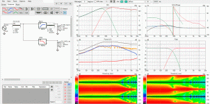
Look how the orange in-room estimate response stays nice at 600Hz, no dip! And without null towards floor in the vertical polar map!
Response is nice because of narrow vertical directivity of the nao10, not because the crossover creates null towards floor like I touted few posts ago.
Alright, looks like we can have nice frequency response towards first reflections, similar to on axis frequency response, AND reduced interference in listening position! Only thing we need is reduce the first reflections as whole with wide bandwidth narrow vertical directivity. Nulls due to interference around crossover frequency do (almost) nothing to these in-room estimate interference nulls.
* narrow band null (see vertical polar map, there is green dot conveniently positioned towards floor around xo frequency) towards floor does almost nothing to dips in the combined response at listening position, the orange in-room estimate. This is because interference is both constructive and destructive! Dip is destructive interference, and if one tries to reduce the dip with parametric EQ in an experiment setup (or with crossover related null, which is similar as parametric EQ but to a certain direction only) it cannot undo whole dip, because there is constructive interference next to it leaving a dip nevertheless!
Here is the experiment. Two ideal sources spaced a little apart to make interference pattern. Red traces are responses of the transducers, black is the combined response.
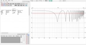
Now, lets get rid of the ~600Hz interference dip shall we, just reduce sound of the second sound on that frequency. That should do it? Nope!
The tip of the dip is gone, but there is constructive interference on both sides still leaving a pretty nasty dip (the black line):
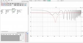
Only very wide EQ, or crossover induced null, could reduce interference dip because constructive interference beside the dip needs to be reduced as well!
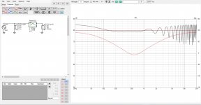
So we come to conclusion that off-axis nulls due to crossover are of no good use! 😀 They could be bad for sound in listening position, and hence Kimmosto 1.4wl c-c rule could apply here as well, on the woofer-mid xo, if it was practical for given application. Another nugget is that only real thing one can do to reduce vertical reflection (showing in the in-room estimate) is wide band narrow vertical directivity.
Does this make sense to you?
I've played with sims a bit today and noticed something that requires straighten up my previous experiment and conclusions.
The 600Hz dip reduction in the in-room estimate I attributed for crossover related null towards the floor, is false! The dip at 600Hz in the in-room response is due to the woofer playing that high, and with the reduced xo frequency the woofer is not paying that high anymore, and not creating the null in the in-room response. My thinking was concentrated on the nulls / destructive interference and forgot constructive interference! *
See this GIF, it is the 450Hz xo from previous experiment with and without the woofer:

Look how the orange in-room estimate response stays nice at 600Hz, no dip! And without null towards floor in the vertical polar map!
Response is nice because of narrow vertical directivity of the nao10, not because the crossover creates null towards floor like I touted few posts ago.
This simple test showed a null around xo towards floor reflection can be manipulated. If height of the transducer(s) and listening distance and xo happens to play together nicely pointing the null can be used as tool to reduce dip due to early floor (and ceiling) reflection. Vertical polar plot shows there is null towards ceiling as well, so that the vertical reflections don't have same frequency response as direct sound. However, the in-room estimate graph is a bit better, no wide dip around 600Hz. Whether this makes sound better, I don't know, but might be since Ken has experienced better sound with roughly similar circumstances and tuneups.
Alright, looks like we can have nice frequency response towards first reflections, similar to on axis frequency response, AND reduced interference in listening position! Only thing we need is reduce the first reflections as whole with wide bandwidth narrow vertical directivity. Nulls due to interference around crossover frequency do (almost) nothing to these in-room estimate interference nulls.
* narrow band null (see vertical polar map, there is green dot conveniently positioned towards floor around xo frequency) towards floor does almost nothing to dips in the combined response at listening position, the orange in-room estimate. This is because interference is both constructive and destructive! Dip is destructive interference, and if one tries to reduce the dip with parametric EQ in an experiment setup (or with crossover related null, which is similar as parametric EQ but to a certain direction only) it cannot undo whole dip, because there is constructive interference next to it leaving a dip nevertheless!
Here is the experiment. Two ideal sources spaced a little apart to make interference pattern. Red traces are responses of the transducers, black is the combined response.

Now, lets get rid of the ~600Hz interference dip shall we, just reduce sound of the second sound on that frequency. That should do it? Nope!
The tip of the dip is gone, but there is constructive interference on both sides still leaving a pretty nasty dip (the black line):

Only very wide EQ, or crossover induced null, could reduce interference dip because constructive interference beside the dip needs to be reduced as well!

So we come to conclusion that off-axis nulls due to crossover are of no good use! 😀 They could be bad for sound in listening position, and hence Kimmosto 1.4wl c-c rule could apply here as well, on the woofer-mid xo, if it was practical for given application. Another nugget is that only real thing one can do to reduce vertical reflection (showing in the in-room estimate) is wide band narrow vertical directivity.
Does this make sense to you?
- Home
- Loudspeakers
- Multi-Way
- After 10 days of planning and 2 days of building; thanks to one forum member / an OB